Electrical length
In telecommunications and electrical engineering, electrical length (or phase length) refers to the length of an electrical conductor in terms of the phase shift introduced by transmission over that conductor[1] at some frequency.
| Part of a series on |
| Antennas |
|---|
 |
Use of the term
Depending on the specific context, the term "electrical length" is used rather than simple physical length to incorporate one or more of the following three concepts:
- When one is concerned with the number of wavelengths, or phase, involved in a wave's transit across a segment of transmission line especially, one may simply specify that electrical length, while specification of a physical length, frequency, or velocity factor is omitted. The electrical length is then typically expressed as N wavelengths or as the phase φ expressed in degrees or radians. Thus in a microstrip design one might specify a shorted stub of 60° phase length, which will correspond to different physical lengths when applied to different frequencies. Or one might consider a 2 meter section of coax which has an electrical length of one quarter wavelength (90°) at 37.5 MHz and ask what its electrical length becomes when the circuit is operated at a different frequency.
- Due to the velocity factor of a particular transmission line, for instance, the transit time of a signal in a certain length of cable is equal to the transit time over a longer distance when travelling at the speed of light. So a pulse sent down a 2 meter section of coax (whose velocity factor is 67%) would arrive at the end of the coax at the same time that the same pulse arrives at the end of a bare wire of length 3 meters (over which it propagates at the speed of light), and one might refer to the 2 meter section of coax as having an electrical length of 3 meters, or an electrical length of ½ wavelength at 50 MHz (since a 50 MHz radio wave has a wavelength of 6 meters).
- Since resonant antennas are usually specified in terms of the electrical length of their conductors (such as the half wave dipole), the attainment of such an electrical length is loosely equated with electrical resonance, that is, a purely resistive impedance at the antenna's input, as is usually desired. An antenna that has been made slightly too long, for instance, will present an inductive reactance, which can be corrected by physically shortening the antenna. Based on this understanding, a common jargon in the antenna trade refers to the achievement of resonance (cancellation of reactance) at the antenna terminals as electrically shortening that too-long antenna (or electrically lengthening a too-short antenna) when an electrical matching network (or antenna tuner) has performed that task without physically altering the antenna's length. Although the terminology is very inexact, this use is widespread, especially as applied to the use of a loading coil at the bottom of a short monopole (a vertical, or whip antenna) to "electrically lengthen" it and achieve electrical resonance as seen through the loading coil.
Phase length
The first use of the term "electrical length" assumes a sine wave of some frequency, or at least a narrowband waveform centered around some frequency f. The sine wave will repeat with a period of T = 1⁄f. The frequency f will correspond to a particular wavelength λ along a particular conductor. For conductors (such as bare wire or air-filled coax) which transmit signals at the speed of light c, the wavelength is given by λ = c⁄f. A distance L along that conductor corresponds to N wavelengths where N; = L⁄λ.
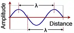
In the figure at the right, the wave shown is seen to be N = 1.5 wavelengths long. A wave crest at the beginning of the graph, moving towards the right, will arrive at the end after a time 1.5 T . The electrical length of that segment is said to be "1.5 wavelengths" or, expressed as a phase angle, "540°" (or 3 π radians) where N wavelengths corresponds to φ = 360°•N (or φ = 2π•N radians). In radio frequency applications, when a delay is introduced due to a transmission line, it is often the phase shift φ that is of importance, so specifying a design in terms of the phase or electrical length allows one to adapt that design to an arbitrary frequency by employing the wavelength λ applying to that frequency.
Velocity factor
In a transmission line, a signal travels at a rate controlled by the effective capacitance and inductance per unit of length of the transmission line. Some transmission lines consist only of bare conductors, in which case their signals propagate at the speed of light, c. More often the signal travels at a reduced velocity κc, where κ is the velocity factor, a number less than 1, representing the ratio of that velocity to the speed of light.[2][3]
Most transmission lines contain a dielectric material (insulator) filling some or all of the space in between the conductors. The relative permittivity or dielectric constant of that material increases the distributed capacitance in the cable, which reduces the velocity factor below unity. It is also possible for κ to be reduced due to a relative permeability () of that material, which increases the distributed inductance, but this is almost never the case. Now, if one fills a space with a dielectric of relative permittivity , then the velocity of an electromagnetic plane wave is reduced by the velocity factor:


- .

This reduced velocity factor would also apply to propagation of signals along wires immersed in a large space filled with that dielectric. However, with only part of the space around the conductors filled with that dielectric, there is less reduction of the wave velocity. Part of the electromagnetic wave surrounding each conductor "feels" the effect of the dielectric, and part is in free space. Then it is possible to define an effective relative permittivity which then predicts the velocity factor according to


is computed as a weighted average of the relative permittivity of free space (1) and that of the dielectric:

where the fill factor F expresses the effective proportion of space so affected by the dielectric.
In the case of coaxial cable, where all of the volume in between the inner conductor and the shield is filled with a dielectric, the fill factor is unity, since the electromagnetic wave is confined to that region. In other types of cable, such as twin lead, the fill factor can be much smaller. Regardless, any cable intended for radio frequencies will have its velocity factor (as well as its characteristic impedance) specified by the manufacturer. In the case of coaxial cable, where F=1, the velocity factor is solely determined by the sort of dielectric used as specified here.
For example, a typical velocity factor for coaxial cable is .66, corresponding to a dielectric constant of 2.25. Suppose we wish to send a 30 MHz signal down a short section of such a cable, and delay it by a quarter wave (90°). In free space, this frequency corresponds to a wavelength of λ0=10m, so a delay of .25λ would require an electrical length of 2.5 m. Applying the velocity factor of .66, this results in a physical length of cable 1.67 m long.
The velocity factor likewise applies to antennas in cases where the antenna conductors are (partly) surrounded by a dieletric. This particularly applies to microstrip antennas such as the patch antenna. Waves on microstrip are affected mostly by the dielectric of the circuit board beneath them, but also on the air above them (because of trace edge effects). Their velocity factors thus depend not directly on the permittivity of the circuit board material but on the effective permittivity which is often specified for a circuit board material (or can be calculated). Note that the fill factor and therefore are somewhat dependent on the width of the trace compared to the thickness of the board.
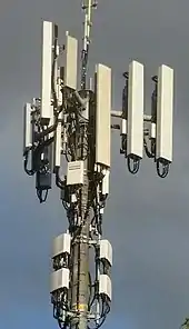
Antennas
While there are certain wideband antenna designs, many antennas are classified as resonant and perform according to design around a particular frequency. This applies especially to broadcasting stations and communication systems which are confined to one frequency or narrow frequency band. This includes the dipole and monopole antennas and all of the designs based on them (Yagi, dipole or monopole arrays, folded dipole, etc.). In addition to the directive gain in beam antennas suffering away from the design frequency, the antenna feedpoint impedance is very sensitive to frequency offsets. Especially for transmitting, the antenna is often intended to operate at the resonant frequency. At the resonant frequency, by definition, that impedance is a pure resistance which matches the characteristic impedance of the transmission line and the output (or input) impedance of the transmitter (or receiver). At frequencies away from the resonant frequency, the impedance includes some reactance (capacitance or inductance). It is possible for an antenna tuner to be used to cancel that reactance (and to change the resistance to match the transmission line), however that is often avoided as an extra complication (and needs to be controlled at the antenna side of the transmission line).
The condition for resonance in a monopole antenna is for the element to be an odd multiple of a quarter-wavelength, λ/4. In a dipole antenna both driven conductors must be that long, for a total dipole length of (2N+1)λ/2.
The electrical length of an antenna element is, in general, different from its physical length [4] [5][6] For example, increasing the diameter of the conductor, or the presence of nearby metal objects, will decrease the velocity of the waves in the element, increasing the electrical length.[7][8]
An antenna which is shorter than its resonant length is described as "electrically short",[9] and exhibits capacitive reactance. Similarly, an antenna which is longer than its resonant length is described as "electrically long" and exhibits inductive reactance.
Changing electrical length by loading
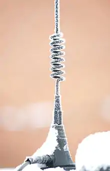
An antenna's effective electrical length can be changed without changing its physical length by adding reactance, (inductance or capacitance) in series with it.[10] This is called lumped-impedance matching or loading.
For example, a monopole antenna such as a metal rod fed at one end, will be resonant when its electrical length is equal to a quarter wavelength, λ/4, of the frequency used. If the antenna is shorter than a quarter wavelength, the feedpoint impedance will include capacitive reactance; this causes reflections on the feedline and a mismatch at the transmitter or receiver, even if the resistive component of the impedance is correct. To cancel the capacitive reactance, an inductance, called a loading coil, is inserted in between the feedline and the antenna terminal. Selecting an inductance with the same reactance as the (negative) capacitative reactance seen at the antenna terminal, cancels that capacitance, and the antenna system (antenna and coil) will again be resonant. The feedline sees a purely resistive impedance. Since an antenna which had been too short now appears as if it were resonant, the addition of the loading coil is sometimes referred to as "electrically lengthening" the antenna.
Similarly, the feedpoint impedance of a monopole antenna longer than λ/4 (or a dipole with arms longer than λ/4) will include inductive reactance. A capacitor in series with the antenna can cancel this reactance to make it resonant, which can be referred to as "electrically shortening" the antenna.
Inductive loading is widely used to reduce the length of whip antennas on portable radios such as walkie-talkies and short wave antennas on cars, to meet physical requirements.
Advantages
The electrical lengthening allows the construction of shorter aerials. It is applied in particular for aerials for VLF, longwave and medium-wave transmitters. Because those radio waves are several hundred meters to many kilometers long, mast radiators of the necessary height cannot be realised economically. It is also used widely for whip antennas on portable devices such as walkie-talkies to allow antennas much shorter than the standard quarter-wavelength to be used. The most widely used example is the rubber ducky antenna.
Disadvantages
The electrical lengthening reduces the bandwidth of the antenna if other phase control measures are not undertaken. An electrically extended aerial is less efficient than the equivalent, full-length antenna.
Technical realization
There are two possibilities for the realisation of the electric lengthening.
- switching in inductive coils in series with the aerial
- switching in metal surfaces, known as roof capacitance, at the aerial ends which form capacitors to earth.
Often both measures are combined. The coils switched in series must sometimes be placed in the middle of the aerial construction. The cabin installed at a height of 150-metres on the Blosenbergturm in Beromünster is such a construction, in which a lengthening coil is installed for the supply of the upper tower part (the Blosenbergturm has in addition a ring-shaped roof capacitor on its top)
Application
Transmission aerials of transmitters working at frequencies below the longwave broadcasting band always apply electric lengthening. Broadcasting aerials of longwave broadcasting stations apply it often. However, for transmission aerials of NDBs electrical lengthening is extensively applied, because these use antennas which are considerably less tall than a quarter of the radiated wavelength.
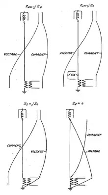
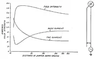 On the left, characteristics plotted from experimentally obtained data on coordinates with logarithmic abscissa. On the right, an antenna with increased effective inductance between the two points in accordance with the well known operation of shunt tuned circuits adjusted somewhat off resonance.
References
- Ron Schmitt, Electromagnetics explained [electronic resource]: a handbook for wireless/RF, EMC, and high-speed electronics. 8
- Carr, Joseph J. (1997). Microwave & Wireless Communications Technology. Newnes. p. 51. ISBN 0750697075.
- Amlaner, Charles J. Jr. (March 1979). "The design of antennas for use in radio telemetry". A Handbook on Biotelemetry and Radio Tracking: Proceedings of an International Conference on Telemetry and Radio Tracking in Biology and Medicine, Oxford, 20–22 March 1979. Elsevier. p. 260. ISBN 9781483189314. Retrieved 23 November 2013.
- Weik, Martin (1997). Fiber Optics Standard Dictionary. Springer Science & Business Media. p. 270. ISBN 0412122413.
-
"Electrical length". Federal Standard 1037C, Glossary of Telecommunication Terms. National Telecommunications & Information Admin., Dept. of Commerce, US Government. 1996. Retrieved November 23, 2014. External link in
|publisher=(help) - Helfrick, Albert D. (2012). Electrical Spectrum & Network Analyzers: A Practical Approach. Academic Press. p. 192. ISBN 978-0080918679.
- Lewis, Geoff (2013). Newnes Communications Technology Handbook. Elsevier. p. 46. ISBN 978-1483101026.
- Carr, Joseph J. (Sep 11, 2001). Antenna Toolkit. 53: (Oxford:Boston:)Newnes. p. 288. ISBN 9780080493886.CS1 maint: location (link)
- Slyusar V. I. 60 Years of Electrically Small Antennas Theory.//Proceedings of the 6-th International Conference on Antenna Theory and Techniques, 17-21 September, 2007, Sevastopol, Ukraine. - Pp. 116 - 118.
- Howard, R. Stephen; Vaughan, Harvey D. (September 1998). NEETS (Navy Electricity and Electronics Training Series) Module 10—Introduction to Wave Propagation, Transmission Lines, and Antennas (NAVEDTRA 14182) (PDF). Naval Education and Training Center, US Navy. pp. 4.17–4.18.
- Terman, Frederick Emmons (1943). Radio Engineer's Handbook. McGraw-Hill. p. 773.
- Kraus, John D (1988). Antennas (PDF) (2 ed.). McGraw-Hill. p. 413. ISBN 0-07-035422-7.
- Balanis, Constatine A. (1997). Antenna Theory. John Wiley & Sons. pp. 151. ISBN 0-471-59268-4.
Further reading
- A. Nickle, U.S. Patent 2,125,804, "Antenna". (Filed May 25, 1934; Issued Aug 2, 1938)
- William W. Brown, U.S. Patent 2,059,186, "Antenna structure". (Filed May 25, 1934; Issued Oct 27, 1936).
- Robert B. Dome, U.S. Patent 2,101,674, "Antenna". (Filed May 25, 1934; Issued Dec 7, 1937)
- Slyusar V. I. 60 Years of Electrically Small Antennas Theory.//Proceedings of the 6-th International Conference on Antenna Theory and Techniques, 17-21 September, 2007, Sevastopol, Ukraine. - Pp. 116 - 118.