Expansion tank
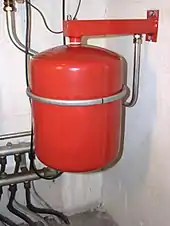
An expansion tank or expansion vessel is a small tank used to protect closed (not open to atmospheric pressure) water heating systems and domestic hot water systems from excessive pressure. The tank is partially filled with air, whose compressibility cushions shock caused by water hammer and absorbs excess water pressure caused by thermal expansion.

Description
The modern vessel is a small container or tank divided in two by a rubber diaphragm. One side is connected to the pipe work of the heating system and therefore contains water. The other, the dry side, contains air under pressure, and normally a Schrader valve (car-tire type valve stem) for checking pressures and adding air. When the heating system is empty or at the low end of the normal range of working pressure, the diaphragm is pushed against the water inlet; as the water pressure increases, the diaphragm moves, compressing the air on its other side.
An older style of expansion tank was larger, oriented horizontally, and had no rubber diaphragm separating the water from the air pocket. This now obsolete style would gradually transfer air from the tank to the highest point in the system, due to air dissolving in the water, and then coming out of solution elsewhere in the system. This in turn required periodic draining of the expansion tank, as well as periodic bleeding of the system, to maintain its effectiveness.
The rubber diaphragm in modern expansion tanks prevents this undesired transfer of air, and helps maintain low levels of oxygen within the pipes, reducing corrosion in the system.
Domestic applications
When expansion tanks are used in domestic hot water (DHW) systems, the tank and the diaphragm must conform to drinking water regulations and must be capable of accommodating the required volume of water.
In the past, domestic plumbing systems often contained more air than they do currently, and the trapped air acted as a crude expansion tank. In new and upgraded systems, expansion tanks are used more frequently than in the past.
In the UK, prior to the use of sealed expansion tanks, "open" tanks were installed in the roof space to accommodate the water's expansion; these had the disadvantage of being exposed to the cold air in the roof space. This, without effective loft insulation, could fall below freezing, and could cause the pipework supplying the tank to freeze. However, with good pipe and tank insulation, this was in practice quite rare. Although such systems were remarkably trouble free, there are concerns about the potability of water from roof tanks due to the possibility of contamination. The other major disadvantage is that the water pressure from a roof tank is considerably lower than mains water pressure, making the use of mixer taps sometimes unpredictable.
Domestic hydronic heating and cooling systems generally include an expansion tank to buffer pressure changes due to expansion and contraction of the water they use for heat transfer.
A minimum pressure of 28–34 kPa; 0.28–0.34 bar (4–5 psi) at the top of a closed hydronic system is suggested.[1]
In Europe the design and the construction of expansion tanks are ruled by EN 13831 according to Pressure Equipment Directive (PED) 97/23/EC.
Automotive applications

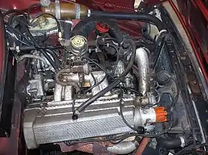
An expansion tank, also known as "overflow bottle", is also used in the cooling system of most internal combustion engines, to allow the coolant, the antifreeze, and the air in the system to expand with rising temperature and pressure. The tank is also called a "coolant recovery tank", since it prevents venting and permanent loss of coolant, by allowing it to be sucked back into the cooling system as the engine cools.
Larger systems
Similar devices are used in large-scale pumping stations, where they may be called an expansion chamber[2] or a hydrophore, to maintain an even pressure and to reduce the effects of water hammer.
See also
References
- ACHR News | Pressurization Of Closed Hydronic Systems
- Jones, Garr M.; Sanks, Robert L.; Bosserman II, Bayard E.; Tchobanoglous, George (6 August 2008). "Vibration and Noise". Pumping Station Design (Rev. 3rd ed.). USA: Butterworth-Heinemann. p. 22.44. ISBN 9781856175135. Retrieved 7 January 2020.