Modified frequency modulation
Modified frequency modulation (MFM) is a run-length limited (RLL) coding scheme[1] used to encode the actual data-bits on most floppy disks. It was first introduced in hard disk drives in 1970 with the IBM 3330 and then in floppy disk drives beginning with the IBM 53FD in 1976.
MFM is a modification to the original frequency modulation (FM) for encoding data on single-density floppy disks and some early hard disk drives.
Due to the minimum spacing between flux transitions that is a property of the disk, head and channel design, MFM, which guarantees at most one flux transition per data bit, can be written at higher density than FM, which can require two transitions per data bit. It is used with a data rate of 250–500 kbit/s (500–1000 kbit/s encoded) on industry-standard 5¼-inch and 3½-inch ordinary and high-density diskettes. MFM was also used in early hard disk designs, before the advent of more efficient types of run-length limited codes. Outside of niche applications, MFM encoding is obsolete in magnetic recording.
Frequency modulation
The digital coding method "frequency modulation" (FM) as used in magnetic storage art has a variety of other names, including delay coding and differential Manchester encoding.[2]
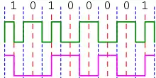
Frequency modulation is the encoding of binary data to form a two-level signal where (a) a "0" causes no change of signal level unless it is followed by another "0" in which case a transition to the other level takes place at the end of the first bit period; and (b) a "1" causes a transition from one level to the other in the middle of the bit period.[3]
FM encoding is used primarily for encoding signals because the frequency spectrum of the encoded signal contains less low-frequency energy than a conventional non-return-to-zero (NRZ) signal and less high-frequency energy than a biphase signal.
FM encoding is an encoding using only half the bandwidth for biphase encoding but features all the advantages of biphase encoding: To be rewritten: It is guaranteed to have transitions every other bit, meaning that decoding systems can adjust their clock/DC threshold continuously. One drawback is that it lacks easy human readability (e.g. on an oscilloscope).
FM encoding is also known as Miller coding after Armin Miller, its inventor.[4]
MFM coding
As is standard when discussing hard drive encoding schemes, FM and MFM encodings produce a bit stream which is NRZI encoded when written to disk. A 1-bit represents a magnetic transition, and a 0-bit no transition. Data encoding has to balance two factors:
- there are limits on the minimum and maximum number of 0-bits that the hardware can detect between consecutive 1-bits, and the encoding must not exceed this limit;
- there are limits on the maximum number of 1-bits that the hardware can detect in a given amount of time. If a disk is encoded with a higher (average) number of magnetic transitions per bit, the bits will have to be "wider" and fewer sectors will fit each track;
Both FM and MFM encodings can also be thought of as having data bits separated by clock bits, but with different rules for encoding the bits. Still, both formats encode each data bit as two bits on disk (because of delimiters that are required at the beginning and end of a sequence, the actual density is slightly lower).
The basic encoding rule for FM is that all clock bits are 1: zeros are encoded as 10, ones are encoded as 11. The number of magnetic transitions per bit is on average 1.5(50% × 1 + 50% × 2).
The basic encoding rule for MFM is that (x, y, z, ...) encodes to (x, x NOR y, y, y NOR z, z, z NOR...). A zero is encoded as 10 if preceded by a zero, and 00 if preceded by a one (each of these cases occurs 25% of the time); a one is always encoded as 01 (which happens 50% of the time); thus the number of magnetic transitions is on average 0.75(25% 10 = yes + 25% 00 = no + 50% 01 = yes).
| Data | ... 0 0 ... | ... 0 1 ... | ... 1 0 ... | ... 1 1 ... |
|---|---|---|---|---|
| MFM clock bits | ...? 1 ?... | ...? 0 0... | ...0 0 ?... | ...0 0 0... |
| MFM encoding | ...?010?... | ...?0010... | ...0100?... | ...01010... |
Note that the surrounding clock bits are sometimes known, but sometimes require knowledge of the adjacent data bits. A longer example:
Data:          0 0 0 1 1 0 1 1 ...
FM encoded:   10101011111011111...
MFM clock:    ? 1 1 0 0 0 0 0 0...
MFM encoded:  ?0101001010001010...
(The bold bits are the data bits, the others are the clock bits.)
In FM encoding, the number of 0-bits that may appear between consecutive 1-bits is either 0 or 1. In MFM encoding there is a minimum of 1 zero bit between adjacent ones (there are never two adjacent one bits), and the maximum number of zeros in a row is 3. Thus, FM is a (0,1) RLL code, while MFM is a (1,3) code.
A special “sync mark” is used to allow the disk controller to figure out where the data starts. This sync mark must follow the RLL code so that the controller can recognize it, but it does not follow the FM and MFM rules for clock bits. This way, it will never occur in any bit position in any encoded data stream. The shortest possible sync bit pattern, which follows the (1,3) RLL coding rules but cannot be produced by normal MFM coding, is 100010010001. In fact, the sync mark that is commonly used in MFM encoding starts with these twelve bits; it is called an “A1 sync” since the data bits form the start of the hexadecimal value A1 (10100001), but the fifth clock bit is different from the normal encoding of the A1 byte.
Data:      1 0 1 0 0 0 0 1
Clock:      0 0 0 1 1 1 0
Encoded:   100010010101001
Sync clock: 0 0 0 1 0 1 0
Sync Mark: 100010010001001
                    ^ Missing clock bit
MMFM
MMFM, (Modified Modified Frequency Modulation), also abbreviated M²FM, or M2FM, is similar to MFM, but suppresses additional clock bits, producing a longer maximum run length (a (1,4) RLL code). In particular, a clock pulse is only inserted between a pair of adjacent 0-bits if the first bit of the pair did not have a clock pulse inserted before it.[5] In the example below, clock bits that would have been present in MFM are noted in bold:
Data:     1 1 0 1 0 0 1 0 0 0 1 0 0 0 0 1 0 0 0 0 0 1
Clock:   0 0 0 0 0 1 0 0 1 0 0 0 1 0 1 0 0 1 0 1 0 0
Encoded: 01010001001001001000010010001001001000100001
In this system, sync marks are made by inserting additional clock pulses between adjacent zero bits (following the MFM rule) where they would normally be omitted. In particular, the data bit pattern "100001" has a clock pulse inserted in the middle, where it would normally be omitted:
Data:  1 0 0 0 0 1
Normal: 0 1 0 1 0
Sync:   0 1 1 1 0
See also
- Group coded recording (GCR)
References
- Kees Schouhamer Immink (December 1990). "Runlength-Limited Sequences". Proceedings of the IEEE. 78 (11): 1745–1759. doi:10.1109/5.63306.
A detailed description is furnished of the limiting properties of runlength limited sequences.
- Hoagland, Al (1963). Digital Magnetic Recording. John Wiley & Sons. p. 127.
The next binary coding technique to be described is variously referred to as the phase modulation method, the frequency modulation method ... and a few other more frequently used terms.
- "Delay Modulation". Proceedings of the IEEE. IEEE. 57 (7). July 1969.
- US Pat. # 3,108,261
- Intel Corporation (1977). SBC 202 Double Density Diskette Controller Hardware Reference Manual (PDF). pp. 4–26. Archived (PDF) from the original on 2017-06-18.
This article is based on material taken from the Free On-line Dictionary of Computing prior to 1 November 2008 and incorporated under the "relicensing" terms of the GFDL, version 1.3 or later.
![]() This article incorporates public domain material from the General Services Administration document: "Federal Standard 1037C".
This article incorporates public domain material from the General Services Administration document: "Federal Standard 1037C".
Further reading
- Savard, John J. G. (2018) [2006]. "Digital Magnetic Tape Recording". quadibloc. Archived from the original on 2018-07-02. Retrieved 2018-07-16.
External links
- Johnson, Herbert R. (2016-07-06). "M2FM or MMFM diskette format". Archived from the original on 2017-06-18. Retrieved 2017-06-19.
- The PC Guide Frequency Modulation
Line coding (digital baseband transmission) | ||
|---|---|---|
| Main articles | 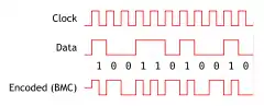 | |
| Basic line codes | ||
| Extended line codes | ||
| Optical line codes | ||
| ||
