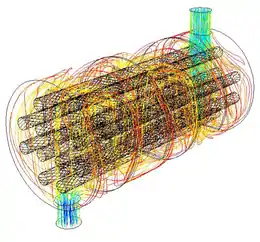
Shell and tube heat exchanger
A shell and tube heat exchanger is a class of heat exchanger designs.[1][2] It is the most common type of heat exchanger in oil refineries and other large chemical processes, and is suited for higher-pressure applications. As its name implies, this type of heat exchanger consists of a shell (a large pressure vessel) with a bundle of tubes inside it. One fluid runs through the tubes, and another fluid flows over the tubes (through the shell) to transfer heat between the two fluids. The set of tubes is called a tube bundle, and may be composed of several types of tubes: plain, longitudinally finned, etc.
Theory and application
Two fluids, of different starting temperatures, flow through the heat exchanger. One flows through the tubes (the tube side) and the other flows outside the tubes but inside the shell (the shell side). Heat is transferred from one fluid to the other through the tube walls, either from tube side to shell side or vice versa. The fluids can be either liquids or gases on either the shell or the tube side. In order to transfer heat efficiently, a large heat transfer area should be used, leading to the use of many tubes. In this way, waste heat can be put to use. This is an efficient way to conserve energy.
Heat exchangers with only one phase (liquid or gas) on each side can be called one-phase or single-phase heat exchangers. Two-phase heat exchangers can be used to heat a liquid to boil it into a gas (vapor), sometimes called boilers, or to cool the vapors and condense it into a liquid (called condensers), with the phase change usually occurring on the shell side. Boilers in steam engine locomotives are typically large, usually cylindrically-shaped shell-and-tube heat exchangers. In large power plants with steam-driven turbines, shell-and-tube surface condensers are used to condense the exhaust steam exiting the turbine into condensate water which is recycled back to be turned into steam in the steam generator.
They are also used in liquid-cooled chillers for transferring heat between the refrigerant and the water in both the evaporator and condenser, and in air-cooled chillers for only the evaporator.
Shell and tube heat exchanger design
There can be many variations on the shell and tube design. Typically, the ends of each tube are connected to plenums (sometimes called water boxes) through holes in tubesheets. The tubes may be straight or bent in the shape of a U, called U-tubes.

In nuclear power plants called pressurized water reactors, large heat exchangers called steam generators are two-phase, shell-and-tube heat exchangers which typically have U-tubes. They are used to boil water recycled from a surface condenser into steam to drive a turbine to produce power. Most shell-and-tube heat exchangers are either 1, 2, or 4 pass designs on the tube side. This refers to the number of times the fluid in the tubes passes through the fluid in the shell. In a single pass heat exchanger, the fluid goes in one end of each tube and out the other.
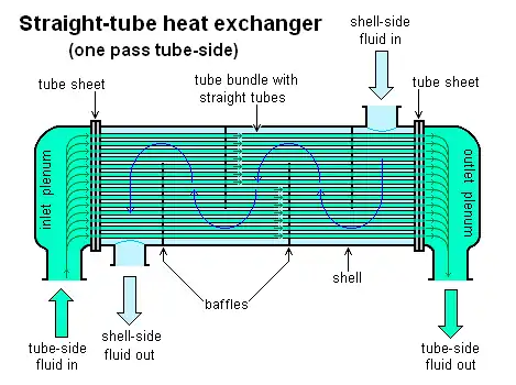
Surface condensers in power plants are often 1-pass straight-tube heat exchangers (see surface condenser for diagram). Two and four pass designs are common because the fluid can enter and exit on the same side. This makes construction much simpler.

There are often baffles directing flow through the shell side so the fluid does not take a short cut through the shell side leaving ineffective low flow volumes. These are generally attached to the tube bundle rather than the shell in order that the bundle is still removable for maintenance.
Counter current heat exchangers are most efficient because they allow the highest log mean temperature difference between the hot and cold streams. Many companies however do not use two pass heat exchangers with a u-tube because they can break easily in addition to being more expensive to build. Often multiple heat exchangers can be used to simulate the counter current flow of a single large exchanger.
Selection of tube material
To be able to transfer heat well, the tube material should have good thermal conductivity. Because heat is transferred from a hot to a cold side through the tubes, there is a temperature difference through the width of the tubes. Because of the tendency of the tube material to thermally expand differently at various temperatures, thermal stresses occur during operation. This is in addition to any stress from high pressures from the fluids themselves. The tube material also should be compatible with both the shell and tube side fluids for long periods under the operating conditions (temperatures, pressures, pH, etc.) to minimize deterioration such as corrosion. All of these requirements call for careful selection of strong, thermally-conductive, corrosion-resistant, high quality tube materials, typically metals, including aluminium, copper alloy, stainless steel, carbon steel, non-ferrous copper alloy, Inconel, nickel, Hastelloy and titanium.[3] Fluoropolymers such as Perfluoroalkoxy alkane (PFA) and Fluorinated ethylene propylene (FEP) are also used to produce the tubing material due to their high resistance to extreme temperatures.[4] Poor choice of tube material could result in a leak through a tube between the shell and tube sides causing fluid cross-contamination and possibly loss of pressure.
Applications and uses
The simple design of a shell and tube heat exchanger makes it an ideal cooling solution for a wide variety of applications. One of the most common applications is the cooling of hydraulic fluid and oil in engines, transmissions and hydraulic power packs. With the right choice of materials they can also be used to cool or heat other mediums, such as swimming pool water or charge air.[5] There are many advantages to shell and tube technology over plates
- One of the big advantages of using a shell and tube heat exchanger is that they are often easy to service, particularly with models where a floating tube bundle is available.[6](where the tube plates are not welded to the outer shell). It is particularly interesting in applications where the cold medium is charged with particles or prone to fouling: it is the case for marine applications[7] and the maintenance of heat exchangers with shell and tube technology is quick and efficient compared to other technologies.
- The cylindrical design of the housing is extremely resistant to pressure and allows all ranges of pressure applications
Overpressure protection
In shell and tube heat exchangers there is a potential for a tube to rupture and for high pressure (HP) fluid to enter and over-pressurise the low pressure (LP) side of the heat exchanger.[8] The usual configuration of exchangers is for the HP fluid to be in the tubes and for LP water, cooling or heating media to be on the shell side. There is a risk that a tube rupture could compromise the integrity of the shell and the release flammable gas or liquid, with a risk to people and financial loss. The shell of an exchanger must be protected against over-pressure by rupture discs or relief valves. The opening time of protection devices has been found to be critical for exchanger protection.[9] Such devices are fitted directly on the shell of the exchanger and discharge into a relief system.
Design and construction standards
- Standards of the Tubular Exchanger Manufacturers Association (TEMA), 10th edition, 2019
- EN 13445-3 "Unfired Pressure Vessels - Part 3: Design", Section 13 (2012)
- ASME Boiler and Pressure Vessel Code, Section VIII, Division 1, Part UHX
See also
- Boiler or Reboiler
- EJMA
- Fired heater
- Fouling or scaling
- Heat exchanger
- NTU method as an alternative to finding the LMTD
- Plate and frame heat exchanger
- Plate fin heat exchanger
- Pressure vessel
- Surface condenser
References
- Sadik Kakaç & Hongtan Liu (2002). Heat Exchangers: Selection, Rating and Thermal Design (2nd ed.). CRC Press. ISBN 0-8493-0902-6.
- Perry, Robert H. & Green, Don W. (1984). Perry's Chemical Engineers' Handbook (6th ed.). McGraw-Hill. ISBN 0-07-049479-7.
- "Shell and Tube Exchangers". Retrieved 2009-05-08.
- "PFA Properties" (PDF). www.fluorotherm.com/. Fluorotherm Polymers, Inc. Retrieved 4 November 2014.
- "Applications and Uses". Retrieved 2016-01-25.
- Heat Exchanger Shell Bellows Piping Technology and Products, (retrieved March 2012)
- "Shell & tubes heat exchangers and oil coolers from MOTA". www.motaindustrialcooling.com. Retrieved 2020-09-29.
- The Energy Institute (2015). Guidelines for the safe design and operation of shell and tube heat exchangers to withstand the impact of tube failure. London: The Energy Institute.
- The Institution of Chemical Engineers (21 March 2018). "Screening Heat Exchangers for High Pressure Differential Relief". The Institution of Chemical Engineers. Retrieved 24 January 2021.
External links
| Wikimedia Commons has media related to Shell and tube heat exchangers. |