Transponder landing system
A transponder landing system (TLS) is an all-weather, precision landing system that uses existing airborne transponder and instrument landing system (ILS) equipment to create a precision approach at a location where an ILS would normally not be available.

Description

Conventional ILS systems broadcast using a number of "single purpose" antennas. The localizer array consists of 8 to 14 or more antenna elements and is typically located 2000+ feet from the runway approach threshold, which is often beyond the departure end of the runway, and provides a fan-shaped signal for azimuth direction (side to side). The other antenna array is located beside the runway and provides elevation to indicate a standard glideslope. ILS installations typically also include two or more "marker beacons" located off the end of the runway to provide distance indications as the aircraft approaches the runway. This complex set of antennas is expensive to install and maintain, and is often difficult to site in areas with uneven terrain or obstacles that could interfere with its guidance signals.
Function
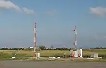
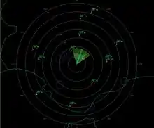
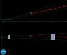
The TLS facility interrogates the transponders of all aircraft within 110 nautical miles (200 km). After receiving a response, TLS determines the aircraft's location using three sets of antenna arrays: one for horizontal position using monopulse techniques, the other for vertical monopulse[1] and a third for trilateration. TLS then calculates the position of all aircraft using the transponder replies and converts that into real-time guidance for an aircraft cleared for approach based on its position relative to the desired approach path. The position tracks for all aircraft in the TLS service volume are displayed on an ATC monitor similar to a secondary surveillance radar but with an increased update rate and higher accuracy. For an aircraft conducting an instrument approach, the TLS will transmit horizontal and vertical guidance signals to the ILS receiver and cockpit avionics that are identical to those of an ILS. The signals will thus appear to emanate from fixed locations where ILS antennas are typically installed. However, TLS guidance is not a function of antenna location - the TLS can provide guidance from "virtual emanation points" that may be anywhere as required by an instrument approach procedure but are configured in the TLS software. This allows the TLS to support multiple approach procedures at a given airport, including steeper glide slope angles for rotary-wing aircraft or increased obstacle clearance, with a single complete system installed adjacent to runway threshold. The TLS will also produce marker beacon-like audio to indicate distance from the runway, but without the requirement for physical equipment. All the pilot has to do is follow the same ATC protocols required for a conventional ILS approach. Any aircraft conducting a PAR-type approach can be viewed on the TLS PAR format console displaying azimuth and elevation. Up to four different aircraft may be viewed independently on four separate consoles to assist PAR controllers with talk-down approaches.
Uses
A TLS can be installed in areas where a conventional ILS would not fit or would not function properly, like, for example, an airport that doesn't have a proper reflecting surface for an ILS glideslope because of uneven terrain like steep hills or mountains, or airports that have large buildings like hangars or parking garages that create disruptive reflections that would prevent an ILS localizer from being used.[2] TLS does not even have to be installed at a particular location relative to the runway, but can "offset" its signals from wherever it is installed to appear as if it were at the end of the runway. This makes it much less expensive to install while still providing ILS-class blind-landing approaches. In 1998, TLS was certified by the FAA for Category I ILS usage.
Radio-navigation aids must keep a certain degree of accuracy (given by international standards such as FAA, ICAO, etc.). To assure this is the case, flight inspection organizations periodically check critical parameters on properly equipped aircraft to calibrate and certify TLS precision.[3]
Benefits
One of the primary benefits of TLS is the ability to provide precision ILS guidance where terrain is sloping or uneven. Reflections can create an uneven glide path for ILS causing unwanted needle deflections. Additionally, since the ILS signals are pointed in one direction by the positioning of the arrays, ILS only supports straight-in approaches. TLS supports approach over rough terrain and provides the ability to offset the approach center-line.
With TLS, the localizer course can have a tailored width at the runway threshold (700 feet and 5 degrees typically) regardless of the runway length. The localizer width characteristics can be selected by the approach designer whereas with an ILS the localizer width is determined by the localizer antenna placement which is usually a consequence of runway length.
For military users, TLS also provides a Precision Approach Radar (PAR) graphic display of aircraft position compared to the desired approach course in order for a PAR operator to provide talk-down guidance to the pilot.[4] Since the TLS operates using the long range band of SSR (1030/1090 MHz) there is no rain fade such as experienced with a traditional PAR that uses primary radar. For a traditional PAR, the ability to track the aircraft position is dependent on the aircraft radar cross section.
TLS is based on transponder multilateration and trilateration and consequently tracks all aircraft that respond to the interrogations. Omnidirectional antenna surveillance coverage of the TLS extends to 60 nautical miles.[4]
The TLS functions using airborne equipment that is currently widely used by the aviation industry. TLS uses the existing Mode 3/A/C/S transponder equipment to determine the aircraft's position. It then transmits the correct signal on the same frequencies used for the current ILS system. All the pilot is required to do is wait for clearance from ATC for the TLS approach and then tune an ILS receiver to the appropriate frequency. TLS uses equipment most airplanes already have.
Drawbacks
Since the TLS simulates an ILS signal that is specific to one aircraft's location, only one aircraft at a time may be cleared for the TLS landing approach. Any other aircraft in the area will receive the same guidance regardless of their location relative to the approach and must wait to be cleared by ATC. The transponder code for the cleared aircraft is selected at the remote control unit.
Variations
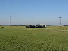
For mobile applications, primarily of interest to the military, there is a variety of electronics packaging available including transportability by trailer, HMMWV or NATO shelter.
See also
Notes
- Winner (2002), pp. 2, 6.
- Winner (2002), pp. 3–6.
- Barbeau (2002), p. 6.
- ANPC (2012) website
References
- Winner, Karl (2002). Application of the Transponder Landing System to Achieve Airport Accessibility
- Barbeau, Charles (2002). Flight Inspection of the Transponder Landing System
- Federal Aviation Administration (December 15, 2004). "Order 8200-40B Flight Inspection of the Transponder Landing System (TLS)" (pdf). Retrieved 2005-12-11. Background section explains operation and use of a TLS.
- ANPC (2012). "TLS commercial products". Archived from the original on November 19, 2010. Retrieved January 2012. Check date values in:
|accessdate=(help)
