Omnidirectional antenna
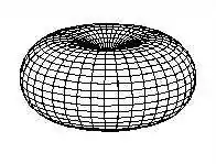
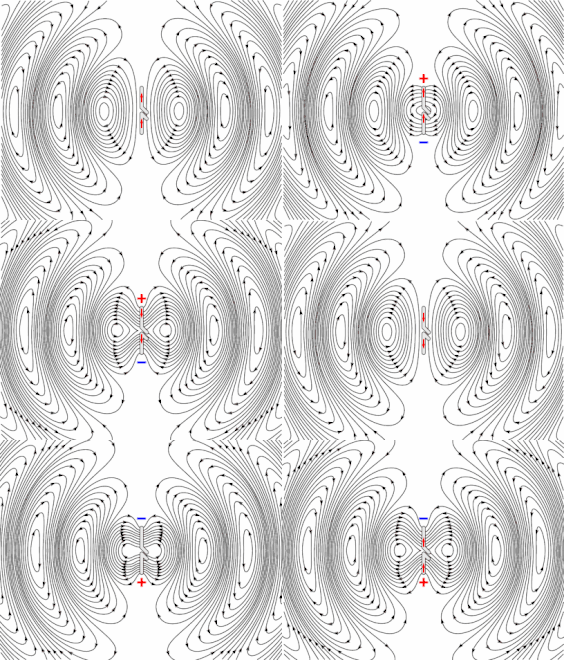
In radio communication, an omnidirectional antenna is a class of antenna which radiates equal radio power in all directions perpendicular to an axis (azimuthal directions), with power varying with angle to the axis (elevation angle), declining to zero on the axis.[1][2] When graphed in three dimensions (see graph) this radiation pattern is often described as doughnut-shaped. Note that this is different from an isotropic antenna, which radiates equal power in all directions, having a spherical radiation pattern. Omnidirectional antennas oriented vertically are widely used for nondirectional antennas on the surface of the Earth because they radiate equally in all horizontal directions, while the power radiated drops off with elevation angle so little radio energy is aimed into the sky or down toward the earth and wasted. Omnidirectional antennas are widely used for radio broadcasting antennas, and in mobile devices that use radio such as cell phones, FM radios, walkie-talkies, wireless computer networks, cordless phones, GPS, as well as for base stations that communicate with mobile radios, such as police and taxi dispatchers and aircraft communications.
Types
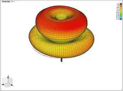
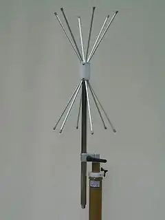
Common types of low-gain omnidirectional antennas are the whip antenna, "Rubber Ducky" antenna, ground plane antenna, vertically oriented dipole antenna, discone antenna, mast radiator, horizontal loop antenna (sometimes known colloquially as a 'circular aerial' because of the shape) and the halo antenna.
Higher-gain omnidirectional antennas can also be built. "Higher gain" in this case means that the antenna radiates less energy at higher and lower elevation angles and more in the horizontal directions. High-gain omnidirectional antennas are generally realized using collinear dipole arrays. These consist of multiple half-wave dipoles mounted collinearly (in a line), fed in phase.[3] The coaxial collinear (COCO) antenna uses transposed coaxial sections to produce in-phase half-wavelength radiators.[4] A Franklin Array uses short U-shaped half-wavelength sections whose radiation cancels in the far-field to bring each half-wavelength dipole section into equal phase. Another type is the Omnidirectional Microstrip Antenna (OMA).[5]
Analysis
Omnidirectional radiation patterns are produced by the simplest practical antennas, monopole and dipole antennas, consisting of one or two straight rod conductors on a common axis. Antenna gain (G) is defined as antenna efficiency (e) multiplied by antenna directivity (D) which is expressed mathematically as: . A useful relationship between omnidirectional radiation pattern directivity (D) in decibels and half-power beamwidth (HPBW) based on the assumption of a pattern shape is:[6]
See also
References
- Balanis, Constantine A.; Ioannides, Panayiotis I. (2007). Introduction to Smart Antennas. Morgan and Claypool. p. 22. ISBN 978-1598291766.
- National Telecommunication Information Administration (1997). Federal Standard 1037C: Glossary of Telecommunications Terms. US General Services Administration. pp. O-3. ISBN 1461732328.
- Johnson, R; Jasik, H, eds. (1984). Antenna Engineering Handbook. McGraw Hill. pp. 27–14.
- Judasz, T., Balsley, B. (March 1989). "Improved Theoretical and Experimental Models for the Coaxial Colinear Antenna". IEEE Transactions on Antennas and Propagation. 37 (3): 289–296. doi:10.1109/8.18724.CS1 maint: multiple names: authors list (link)
- Bancroft R (December 5, 2005). "Design Parameters of an Omnidirectional Planar Microstrip Antenna". Microwave and Optical Technology Letters. 47 (5): 414–8. doi:10.1002/mop.21187.
- McDonald, Noel (April 1999). "Omnidirectional Pattern Directivity in the Presence of Minor Lobes: Revisited". IEEE Transactions on Antennas and Propagation. 41 (2): 63–8. doi:10.1109/74.769693.