Antenna tuner
Antenna tuner, matching network, matchbox, transmatch, antenna tuning unit (ATU), antenna coupler, and feedline coupler are all equivalent names for a device connected between a radio transmitter and its antenna, to improve power transfer between them by matching the load impedance of the radio to the combined input impedance of the feedline and the antenna.
Antenna tuners are particularly important for use with transmitters. Transmitters are typically designed to feed power into a reactance-free, resistive load of a specific value: 50 ohms, by modern convention.[1] However the antenna and feedline impedance can vary depending on frequency and other factors. If the impedance seen by the transmitter departs from the design load, circuits in modern transmitters automatically cut back the power output to protect the equipment from the consequences of the impedance mismatch.
In addition to reducing the power radiated by the antenna, the mismatch can distort the signal, and in high power transmitters may overheat the transmitter. Because of this, ATUs are a standard part of almost all radio transmitting systems. They may be a circuit incorporated into the transmitter itself, or a separate piece of equipment connected between the transmitter and the antenna. In transmitting systems with an antenna separated from the transmitter and connected to it by a transmission line (feedline), there may be yet another matching network (or ATU) where the feedline connects to the antenna, to match the transmission line's impedance to the antenna.
Transmitters in cell phones and walkie-talkies have an ATU circuit inside permanently set to work with the installed antenna.[lower-alpha 1] In multi-frequency communication stations like amateur radio stations, and high power transmitters like radio broadcasting stations, the ATU is adjustable to accommodate changes in the transmitting system or its environment.[lower-alpha 2] Instruments such as SWR meters, antenna analyzers, or impedance bridges are used to measure the degree of match or mismatch. Adjusting the ATU to match the transmitter to the feedline and antenna is an important procedure done after any change perturbs the antenna system or its environment.
Overview
Antenna tuners are particularly important for use with transmitters. Transmitters are designed to feed power into a resistive load of a specific value, very often 50 Ohms.[1] If the impedance seen by the transmitter departs from this design value due to improper tuning of the combined feedline and antenna, overheating of the transmitter final stage, distortion, or loss of output power may occur.
Use in transmitters
Antenna tuners are used almost universally with transmitters. Without an ATU, in addition to reducing the power radiated by the antenna, the reflected current can overheat transformer cores and cause signal distortion. In high-power transmitters it may overheat the transmitter's output amplifier. When reflected power is detected, self-protection circuits in modern transmitters automatically reduce power to safe levels, hence reduce the power of the signal leaving the antenna even further.
Because of this, ATUs are a standard part of almost all radio transmitting systems. They may be a circuit incorporated into the transmitter itself,[lower-alpha 1] or a separate piece of equipment connected between the transmitter and the antenna. In transmitting systems with an antenna separated from the transmitter and connected to it by a transmission line (feedline), there may be another matching network (or ATU) at the antenna that matches the transmission line's impedance to the antenna.
High power transmitters like radio broadcasting stations have a matching unit that is adjustable to accommodate changes in the transmit frequency, the transmitting unit, the antenna, or the antenna's environment. Adjusting the ATU to match the transmitter to the antenna is an important procedure which is done after any work on the transmitter or antenna occurs, or any drastic change in the weather affecting the antenna (e.g. hoar frost or dust storms).
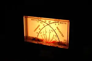
The effect of this adjustment is typically measured using an instrument called an SWR meter, which indicates the degree of mismatch between a reference impedance (typically 50 + j 0 Ohms) and the complex impedance at the point of insertion of the SWR meter. Other instruments such as antenna analyzers, or impedance bridges, provide more detailed information, such as the separate mismatches of the resistive and reactive parts of the impedance on the input and output sides of the ATU.
What an "antenna tuner" actually tunes
Despite its name, an antenna "tuner" does not actually tune the antenna. It matches the resistive (real) impedance of the transmitter to the complex impedance presented by the input end of the feedline. The transmission line will show a different input impedance from the feedline's characteristic impedance, if the impedance of the antenna on the other end of the line does not match the line's characteristic impedance. The consequence of the mismatch is to raise out-of-phase voltage standing waves and current standing waves on the feedline, or equivalently, the line's impedance (voltage to current ratio and phase) will oscillate along the length of line.
If both the tuner and the feedline were lossless, tuning at the transmitter end would indeed produce a perfect match at every point in the transmitter-feedline-antenna system.[2] However, in practical systems lossy feedlines limit the ability of the antenna tuner to change the antenna's resonant frequency. If the loss of power is low in the line carrying the transmitter's signal to the antenna, a tuner at the transmitter end can produce a worthwhile degree of matching and tuning for the antenna and feedline network as a whole.[3][4] But with lossy, low-impedance feedlines like the commonly used 50 Ohm coaxial cable, maximum power transfer occurs only if matching is done at the antenna in conjunction with a matched transmitter and feedline, producing a match at both ends of the line.
In any case, regardless of its placement, an ATU does not alter the gain, efficiency, or directivity of the antenna, nor does it change the internal complex impedance of the antenna, itself.
Efficiency and SWR
If there is still a high standing wave ratio (SWR) in the feedline beyond the ATU, any loss in that part of the feedline is typically increased by the transmitted waves reflecting back and forth between the tuner and the antenna, causing resistive losses in the wires and possibly the insulation of the transmission line. Even with a matching unit at both ends of the feedline – the near ATU matching the transmitter to the feedline and the remote ATU matching the feedline to the antenna – losses in the circuitry of the two ATUs will slightly reduce power delivered to the antenna.
- The most efficient use of a transmitter's power is to use a resonant antenna, fed with a matched-impedance feedline; there are still small losses in any feedline even when all impedances match, but matching minimizes loss.
- It is almost as efficient to feed a remote antenna tuner attached directly to the antenna, via a feedline matched to the transmitter and the ATU feed; the only extra losses are in the tuner circuitry, which can be kept small if the tuner is correctly adjusted and the line carefully tested at or near the antenna.
- It is usually inefficient to operate an antenna far from one of its resonant frequencies and attempt to compensate with an ATU next to the transmitter, far from the antenna; the entire feedline from the ATU to the antenna is still mismatched, which will aggravate normal loss in the feedline, particularly if it is low-impedance line, like standard 50 Ohm coax.
- The least efficient way to transmit, is to feed a non-resonant antenna through lossy feedline with no impedance matching anywhere along the line.
Use in receivers
ATUs are not widely used in shortwave receivers, and almost never used in mediumwave or longwave receivers. They are, however, needed for receivers operating in the upper HF and VHF and above.
In a receiver, if the complex impedance of the antenna is not a conjugate match for the complex input impedance at the antenna end of the transmission line, then some of the incoming signal power will be reflected back out to the antenna and will not reach the receiver. However this is only important for frequencies at and above the middle HF band. In radio receivers working below 20 MHz, atmospheric radio noise dominates the signal to noise ratio (SNR) of the incoming radio signal, and the power of the atmospheric noise that arrives with the signal is far greater than the inherent thermal radio noise generated within the receiver's own circuitry. Therefore, the receiver can amplify the weak signal to compensate for any inefficiency caused by impedance mismatch without perceptibly increasing noise in the output.
At higher frequencies, however, receivers encounter very little atmospheric noise and noise added by the receiver's own front end amplifier dominates the signal to noise ratio. At frequencies above 20 MHz the internal circuit noise is the factor limiting sensitivity of the receiver for weak signals, and so as the frequency rises it becomes increasingly important that the antenna complex impedance be conjugately matched to the input impedance at the antenna end of the transmission line, to transfer the maximum available power from a weak signal into the first amplifier to provide a stronger signal than its own internally-generated noise. So impedance-matching circuits are incorporated in some receivers for the upper HF band, such as CB radio, and for most VHF and higher frequency receivers, such as FM broadcast receivers, and scanners for aircraft and public safety radio.
Broad band matching methods
Transformers, autotransformers, and baluns are sometimes incorporated into the design of narrow band antenna tuners and antenna cabling connections. They will all usually have little effect on the resonant frequency of either the antenna or the narrow band transmitter circuits, but can widen the range of impedances that the antenna tuner can match, and/or convert between balanced and unbalanced cabling where needed.
Ferrite transformers
Solid-state power amplifiers operating from 1–30 MHz typically use one or more wideband transformers wound on ferrite cores. MOSFETs and bipolar junction transistors typically used in modern radio frequency amplifiers are designed to operate into a low impedance, so the transformer primary typically has a single turn, while the 50 Ohm secondary will have 2 to 4 turns. This design of feedline system has the advantage of reducing the retuning required when the operating frequency is changed.
A similar design can match an antenna to a transmission line: For example, many TV antennas have a 300 Ohm impedance but feed the signal to the TV through a 75 Ohm coaxial line. A small ferrite core transformer makes the broad band impedance transformation. This transformer does not need, nor is it capable of adjustment. For receive-only use in a TV the small SWR variation with frequency is not a major problem.
Also note that many ferrite transformers perform a balanced-to-unbalanced transformation in addition to the impedance change. When the balanced to unbalanced function is present these transformers are called a balun (otherwise an unun). The most common baluns have either a 1:1 or a 1:4 impedance transformation.
Autotransformers
There are several designs for impedance matching using an autotransformer, which is a simple, single-wire transformer with different connection points or taps spaced along the coil windings. They are distinguished mainly by their impedance transform ratio,[lower-alpha 3] and whether the input and output sides share a common ground, or are matched from a cable that is grounded on one side (unbalanced) to an ungrounded (usually balanced) cable. When autotransformers connect balanced and unbalanced lines they are called baluns, just as two-winding transformers are.[lower-alpha 4]
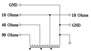
The circuit pictured at the right has three identical windings wrapped in the same direction around either an "air" core (for very high frequencies) or ferrite core (for middle frequencies) or a powdered-iron core (for very low frequencies). The three equal windings shown are wired for a common ground shared by two unbalanced lines (so this design is an unun), and can be used as 1:1, 1:4, or 1:9 impedance match, depending on the tap chosen.[lower-alpha 5]
For example, if the right-hand side is connected to a resistive load of 10 Ohms, the user can attach a source at any of the three ungrounded terminals on the left side of the autotransformer to get a different impedance. Notice that on the left side, the line with more windings between the line's tap-point and the ground tap measures greater impedance for the same 10 Ohm load on the right.
Narrow band design
The "narrow-band" methods described below cover a very much smaller span of frequencies, by comparison with the broadband methods described above.
Antenna matching methods that use transformers tend to cover a wide range of frequencies. A single, typical, commercially available balun can cover frequencies from 3.5–30.0 MHz, or nearly the entire shortwave band. Matching to an antenna using a cut segment of transmission line (described below) is perhaps the most efficient of all matching schemes in terms of electrical power, but typically can only cover a range about 3.5–3.7 MHz wide in the HF band – a very small range indeed, compared to the 27 MHz bandwidth of a well-made broadband balun.
Antenna coupling or feedline matching circuits are also narrowband for any single setting, but can be re-tuned more conveniently. However they are perhaps the least efficient in terms of power-loss (aside from having no impedance matching at all!).
Transmission line antenna tuning methods
There are two different impedance matching techniques using sections of feedline: Either the original feedline can have a deliberately mismatched section of line spliced into it (called section matching), or a short stub of line can branch off from the original line, with the stub's end either shorted or left unconnected (called stub matching). In both cases, the location of the section of extra line on the original feedline and its length require careful placement and adjustment.
Section matching
A special section of transmission line can be used to match the main line to the antenna, if that line section's characteristic impedance is different from that of the main line. The technique is essentially to fix a mismatch by creating an opposite mismatch: A line segment with the proper impedance and proper length, inserted at the proper distance from the antenna, can perform complicated matching effects with very high efficiency. The drawback is that matching with line segments only works for a very limited frequency range for which the segment's length and position are appropriate.[5]
The simplest example this method is the quarter-wave impedance transformer formed by a section of mismatched transmission line. If a quarter-wavelength of 75 Ohm (75 Ω) coaxial cable is linked to a 50 Ω load, the SWR in the 75 Ω quarter wavelength of line can be calculated as 75 Ω⁄50 Ω = 1.5; the quarter-wavelength of line transforms the mismatched impedance to 112.5 Ω (75 Ω × 1.5 = 112.5 Ω). Thus this inserted section matches a 112 Ω antenna to a 50 Ω main line.
The 1⁄6 wavelength coaxial transformer is a useful way to match 50 to 75 Ω using the same general method.[6][7]
Stub matching
A second common method is the use of a stub: Either a shorted or open section of line is connected in parallel with the main feedline, forming a dead-end branch off the main line. With coax this is done using a ‘T’-connector. A stub less than a quarter-wave long whose end is short-circuited acts as an inductor; if its end is left unconnected (open), the stub acts as a capacitor; for lengths between a quarter and a half wave, the reactive behavior is opposite.[8][lower-alpha 6][lower-alpha 7]
The length of the stub and its location is chosen so that its susceptance will be equal-and-opposite to the susceptance at that point on the line, and the remaining, non-reactive impedance will match the line below the stub, removing the effects of the complex impedance or SWR from the antenna.[8]
The J-pole antenna and the related Zepp antenna are both examples of an antenna with a built-in stub match.
Basic lumped circuit matching using the L-network
An ‘L’-network is the simplest circuit that will achieve the desired transformation; for any one given antenna and frequency, once a circuit is selected from the eight possible configurations (of which six are shown in the diagram below) only one set of component values will match the in impedance to the out impedance. Commercially available automatic antenna tuners most often are ‘L’-networks, since they involve the least number of parts and have a unique setting for the adjustment circuitry to seek out.
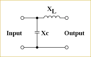
The basic circuit required when lumped capacitances and inductors are used is shown in the schematic below. This circuit is important in that many automatic antenna tuners use it, and also because more complicated circuits can be analyzed as groups of L-networks.
This circuit is called an “L” network not because it contains an inductor (in fact some L-networks consist of two capacitors) but rather because in the schematic the two components are at right angles to each other, having the shape of a rotated and sometimes reversed Roman letter ‘L’. The ‘T’ (“Tee”) network and the ‘π’ (“Pi”) network also have their parts laid out in a shape similar to the Roman and Greek letters they are named after.
This basic network is able to act as an impedance transformer. If the output has an impedance consisting of resistive part Rload and reactive part Xload, which add to make a single complex number (j² = −1). The input is to be attached to a source which has an impedance of Rsource resistance and Xsource reactance, then

and
- .

In this example circuit, XL and XC can be swapped. All the ATU circuits below create this network, which exists between systems with different impedances.
For instance, if the source has a resistive impedance of 50 Ω and the load has a resistive impedance of 1000 Ω :


If the frequency is 28 MHz,
As,

then,

So,

While as,

then,

Theory and practice
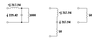
A parallel network, consisting of a resistive element (1000 Ω) and a reactive element (−j 229.415 Ω), will have the same impedance and power factor as a series network consisting of resistive (50 Ω) and reactive elements (−j 217.94 Ω).
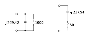
By adding another element in series (which has a reactive impedance of +j 217.94 Ω), the impedance is 50 Ω (resistive).
Types of L-networks and their uses
The L-network can have eight different configurations, six of which are shown in the diagrams at the right. The two omitted configurations are the same as the bottom row, but with the parallel element (wires vertical) on the right side of the series element (wires horizontal), instead of on the left, as shown.
In discussion of the diagrams that follows the in connector comes from the transmitter or "source" on the left; the out connector goes to the antenna or "load" on the right. The general rule (with some exceptions, described below) is that the horizontal element of an L-network goes in series with the side that has the lowest resistive impedance.[9]
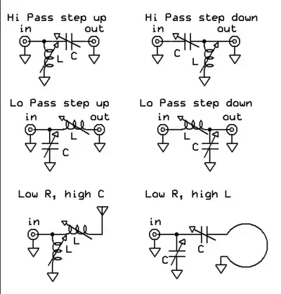
So for example, the three circuits in the left column and the two in the bottom row have the series (horizontal) element on the out side are generally used for stepping up from a low-impedance input (transmitter) to a high-impedance output (antenna), similar to the example analyzed in the section above. The top two circuits in the right column, with the series (horizontal) element on the in side, are generally useful for stepping down from a higher input to a lower output impedance.
The general rule only applies to loads that are mainly resistive, with very little reactance. In cases where the load is highly reactive – such as an antenna fed with a signal whose frequency is far away from any resonance – the opposite configuration may be required. If far from resonance, the bottom two step down (high-in to low-out) circuits would instead be used to connect for a step up (low-in to high-out that is mostly reactance).[10]
The low- and high-pass versions of the four circuits shown in the top two rows use only one inductor and one capacitor. Normally, the low-pass would be preferred with a transmitter, in order to attenuate harmonics, but the high-pass configuration may be chosen if the components are more conveniently obtained, or if the radio already contains an internal low-pass filter, or if attenuation of low frequencies is desirable – for example when a local AM station broadcasting on a medium frequency may be overloading a high frequency receiver.
In the bottom row, the Low R, high C circuit is shown feeding a short vertical antenna, such as would be the case for a compact, mobile antenna or otherwise on frequencies below an antenna's lowest natural resonant frequency. Here the inherent capacitance of a short, random wire antenna is so high that the L-network is best realized with two inductors, instead of aggravating the problem by using a capacitor.
The Low R, high L circuit is shown feeding a small loop antenna. Below resonance this type of antenna has so much inductance, that more inductance from adding a coil would make the reactance even worse. Therefore, the L-network is composed of two capacitors.
Unbalanced Line Tuners
In contrast to two-element L-networks, the circuits described below all have three or more components, and hence have many more choices for inductance and capacitance that will produce an impedance match. The radio operator must experiment, test, and use judgement to choose among the many adjustments that match the same impedances. This section discusses circuit designs for unbalanced lines; it is followed by a section that discusses tuners for balanced lines.
High-pass T-network
This configuration is currently popular because it is capable of matching a large impedance range with capacitors in commonly available sizes. However, it is a high-pass filter and will not attenuate spurious radiation above the cutoff frequency nearly as well as other designs (see the π-network section, below). Due to its low losses and simplicity, many home-built and commercial manually tuned ATUs use this circuit. The tuning coil is normally also adjustable (not shown).
Theory and practice
If a source impedance of 200 Ω and a resistive load of 1000 Ω are connected (via a capacitor with an impedance of −j 200 Ω) to the inductor of the transmatch, vector mathematics can transform this into a parallel network consisting of a resistance of 1040 Ω and a capacitor with an admittance of 1.9231×10⁻⁴ siemens (XC = 5200 Ω).
A resistive load (RL) of 1000 Ω is in series with XC −j 200 Ω.

The phase angle is

- Y = 1⁄Z = 9.8058×10⁻⁴ S
To convert to an equivalent parallel network


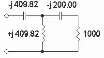
If the reactive component is ignored, a 1040 Ω to 200 Ω transformation is needed (according to the equations above, an inductor of +j 507.32 Ω). If the effect of the capacitor (from the parallel network) is taken into account, an inductor of +j 462.23 Ω is needed. The system can then be mathematically transformed into a series network of 199.9 Ω resistive and +j 409.82 Ω reactive.
A capacitor (−j 409.82) is needed to complete the network. The steps are shown here. Hover over each circuit for captions.
 Circuit as seen by user; parts impedance shown on diagram
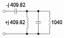 After one transformation (unlabeled part impedance is -j 5200Ω)
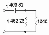 After two transformations
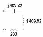 After three transformations
 After four transformations
Low-pass π network
A π (pi) network can also be used. This ATU has very good attenuation of harmonics and was incorporated into the output stage of tube-based ‘vintage’ transmitters and many modern tube-based RF amplifiers. However, the standard π circuit is not popular for stand-alone multiband antenna tuners, since the variable capacitors needed for the lower Amateur bands are inconveniently large and expensive.
Drake’s modified π-network
A modified version of the π-network is more practical as it uses a fixed input capacitor, which can be several thousand picofarads, allowing the two variable capacitors to be smaller. A band switch selects the input capacitor and inductor.[11] This circuit was used in tuners covering 1.8–30 MHz made by the R. L. Drake Company.
SPC tuner
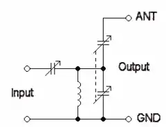
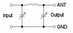
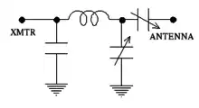
The Series Parallel Capacitor or SPC tuner uses a band-pass circuit that can serve both as an antenna coupler and as a preselector. The following is a simplified description of the SPC circuit:[lower-alpha 8] In the diagram, the upper capacitor on the right matches impedance to the antenna, and the single capacitor on the left matches impedance to the transmitter. The coil and the lower-right capacitor form a tank circuit that drains to ground out-of-tune signals. The coil is usually also adjustable (not shown), in order to widen or narrow the band-pass and to ensure that the ganged right-hand capacitors will be able to both match to the antenna and tune to the transceiver's operating frequency without compromising one or the other.[12]
Ultimate Transmatch
Originally, the Ultimate Transmatch was promoted as a way to make the components more manageable at the lowest frequencies of interest and also to get some harmonic attenuation. A version of McCoy's Ultimate Transmatch network is shown in the illustration to the right.[13]
It is now considered obsolete; the design goals were better realized using identical parts by the Series-Parallel Capacitor (SPC) network, shown above, which was designed after the name Ultimate had already been used.[12]
Balanced line tuners
Balanced (open line) transmission lines require a tuner that has two "hot" output terminals, rather than one "hot" terminal and one "cold" (grounded). Since all modern transmitters have unbalanced (co-axial) output – almost always 50 Ω – the most efficient system has the tuner provide a balun (balanced to unbalanced) transformation as well as providing an impedance match. The tuner usually includes a coil, and the coil can accept or produce either balanced or unbalanced input or output, depending on where the tap points are placed on the coil.
Balanced versions of unbalanced tuner circuits
All of the unbalanced tuner circuits described in the preceding main section can be converted to an equivalent balanced circuit, as follows:
- In standard schematic drawings that have the ground connection as a line along the bottom, one merely draws an upside-down copy of the same circuit, beneath the original, with its ground-line running along the top, and with the components in the same left-to-right orientation.
- In the second step both ground lines are erased and the descending ground connections from the original circuit are wired to their corresponding ascending ground connections in the new, upside-down circuit.
- The components so-joined are either replaced with their combined equivalent, or optionally can have their junction connected to an RF ground.[lower-alpha 9] Where paired components remain, they are "ganged" mechanically, so that one adjustment makes the same change to both.
- In the final step, the unbalanced feed from the transmitter is coupled to the two inputs of the twinned circuit through a balun. The doubled output lines serve as the two "hot" feeds to the balanced antenna.
Commercially available "inherantly balanced" tuners are made as balanced versions of L, T, and π circuits. Their drawback is that the components used for the upper line and the lower line must be carefully matched and attached pairs, so that adjusting them causes an identical tuning change to both "hot" sides of the circuit. Hence, most "inherently balanced" tuners are more than twice as expensive as unbalanced tuners.
Tuned-transformer balanced circuits
The following balanced circuit types have been used for tuners, illustrated in the diagram below. They are all based on tuned transformer circuits; none are balanced versions of the unbalanced circuits discussed above.
Optional and mandatory grounding connections
All of the circuits show a ground connection (a downward pointing triangle) on the antenna side (right hand side). The antenna ground on the right is optional; if used it effectively forces balanced voltage against ground on the two output terminals.[lower-alpha 9] The triangle on the left represents a mandatory ground, and is wired to the signal line connected to the transmitter.[lower-alpha 10][lower-alpha 11]

Fixed link with taps
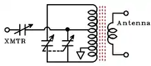
The Fixed link with taps (top left on the diagram) is the most basic circuit. The factor will be nearly constant and is set by the number of relative turns on the input link. The match is found by tuning the capacitor and selecting taps on the main coil, which may be done with a switch accessing various taps or by physically moving clips from turn to turn. If the turns on the main coil are changed to move to a higher or lower frequency, the link turns should also change.

Hairpin tuner
The Hairpin tuner (top right) has the same circuit, but uses a “hairpin” inductor (a tapped transmission line, short-circuited at the far end).[14] Moving the taps along the hairpin allows continuous adjustment of the impedance transformation, which is difficult with a solenoid coil. It is useful for very short wavelengths from about 10 meters to 70 cm (frequencies about 30 MHz to 430 MHz) where the solenoid inductor would have too few turns to allow fine adjustment. These tuners typically operate over at most a 2:1 frequency range.
Series cap with taps
The illustration shows two versions of essentially the same circuit: Series cap with taps and an alternate configuration For low-Z lines. Series cap with taps (middle, left) adds a series capacitor to the input side of the Fixed link with taps. The input capacitor allows fine adjustment with fewer taps on the main coil. An alternate connection (middle, right) for the series cap circuit is useful for low impedances only, but avoids the taps (For low-Z lines in the illustration).
Swinging link with taps
Swinging link with taps (bottom left). A swinging link inserted into the Fixed Link With Taps also allows fine adjustment with fewer coil taps. The swinging link is a form of variable transformer, that moves the input coil in and out of the space between turns in the main coil to change their mutual inductance. The variable inductance makes these tuners more flexible than the basic circuit, but at some cost in complexity.
Fixed link with differential capacitors
Fixed link with differential capacitors (bottom right). The circuit with differential capacitors was the design used for the well-regarded Johnson Matchbox (JMB) tuners.
The four output capacitors sections (C2) are a double-differential capacitor: The axes of the four sections are mechanically connected and their plates aligned so that as the top and bottom capacitor sections increase in value the two middle sections decrease in value, and vice versa. This provides a smooth change of loading that is electrically equivalent to moving taps on the main coil. The Johnson Matchbox used a band switch to change the turns on the main inductor for each of the five frequency bands available to hams in the 1950s. Later, similar designs also have switched taps on the link (input) inductor.
The JMB design has been criticized since the two middle-section capacitors in C2 are not strictly necessary to obtain a match; however, the middle sections conveniently limit the disturbance of the adjustment for C1 caused by changes to C2.
Z match
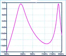
The Z-Match is an ATU widely used for low-power amateur radio which is commonly used both as an unbalanced and as a balanced tuner.[15][16] The Z match has three tuning capacitors, two of which are ganged with separate connections to the primary transformer coil, producing two distinct resonant frequencies that enable it to cover a wide frequency range without switching the inductor. Because it uses a transformer on the output side, it can be used with either balanced or unbalanced transmission lines, without any modification to the tuner circuit. All of the capacitors must be isolated from ground.
The Z-match design is limited in its power output by the core used for the output transformer. A powdered iron or ferrite core about 1.6 inches in diameter should handle 100 watts. A tuner built for low-power use (“QRP” – typically 5 watts or less) can use a smaller core.
Unbalanced tuner and a balun
Another approach to feeding balanced lines is to use an unbalanced tuner with a balun on either the input (transmitter) or output (antenna) side of the tuner. Most often using the popular high pass T circuit described above, with either a 1:1 current balun on the input side of the unbalanced tuner or a balun (typically 4:1) on the output side. It can be managed, but doing so both efficiently and safely is not easy.
Balun between the antenna and the ATU
Any balun placed on the output (antenna) side of a tuner must be built to withstand high voltage and current stresses, because of the wide range of impedances it must handle.[17]
For a wide range of frequencies and impedances it may not be possible to build a robust balun that is adequately efficient. For a narrow range of frequencies, using transmission line stubs or sections for impedance transforms (described above) may well be more feasible and will certainly be more efficient.
Balun between the transmitter and the ATU
The demands put on the balun are more modest if the balun is put on the input end of the tuner – between the tuner and the transmitter. Placed on that end it always operates into a constant 50 Ω impedance from the transmitter on one side, and has the matching network to protect it from wild swings in the feedline impedance on the other side. All to the good. Unfortunately, making the input from the transmitter balanced creates problems that must be remedied.
If an unbalanced tuner is fed with a balanced line from a balun instead of directly from the transmitter, then its normal antenna connection – the center wire of its output coaxial cable – provides the signal as usual to one side of the antenna. However the ground side of that same output connection must now feed an equal and opposite current to the other side of the antenna.
The "true" ground voltage at the antenna and transmitter must lie halfway between the two "hot" feeds, one of which is the internal ground: Inside the ATU, the matching circuit's "false" ground level is equally different from the "true" ground level at either the antenna or the transmitter as the original "hot" wire is (but with opposite polarity). Either the "hot" output wire or the matching circuit "ground" will give you exactly the same shock if you touch it.
The tuner circuit must "float" above or below the exterior ground level in order for the ATU circuit ground (or common side) to feed the second hot wire that formerly was attached to the output cable's ground wire: The circuit's floating ground must provide a voltage difference adequate to drive current through an output terminal to make the second output "hot".[18]
High voltages are normal in any efficient impedance matching circuit bridging a wide mismatch. Unless the incompatible grounds are carefully kept separate, the high voltages present between this interior floating ground and the exterior transmitter and antenna grounds can lead to arcing, corona discharge, capacitively coupled ground currents, and electric shock.
Keeping the mismatched grounds apart
To reduce power loss and protect the operator and the equipment, the tuner chassis must be double-layered: An outer chassis and an inner chassis. The outer chassis must enclose and insulate the tuning circuit and its floating ground from the outside, while itself remaining at the level of the exterior ground(s). With the protective outer chassis, the inner chassis can maintain its own incompatible "floating ground" level, safely isolated.
The inner chassis can be reduced to nothing more than a mounting platform inside the outer chassis, elevated on insulators to keep a safe distance between the "floating ground" and the "true" electrical ground line(s) wired to the outer chassis. The inner tuning circuit's metal mounting chassis, and in particular the metal rods connected to adjustment knobs on the outer chassis must all be kept separate from the surface touched by the operator and from direct electrical contact with the transmitter's ground on its connection cable ("true" ground).
Isolating the controls is usually done by replacing at least part of the metal connecting rods between knobs on the outside surface and adjustable parts on the inside platform with an insulated rod, either made of a sturdy ceramic or a plastic that tolerates high temperatures. Further, the metal inner and outer parts must be adequately distant to prevent current leaking out via capacitive coupling when the interior voltages are high. Finally, all these arrangements must be secured with greater than usual care, to ensure that jostling, pressure, or heat expansion cannot create a contact between the inner and outer grounds.
Summary
Using an inherently unbalanced circuit for a balanced tuner puts difficult constraints on the tuner's construction and high demands on the builder's craftsmanship. The advantage of such a design is that its inner, inherently unbalanced matching circuit always requires only a single component where a balanced version of the same circuit often requires two. Hence it does not require identical pairs of components for the two "hot" ends of the circuit(s) in order to ensure balance to ground within the ATU, and its output is inherently balanced with respect to the exterior "true" ground, even though the interior circuit is unbalanced with respect to the interior "false" ground.
Antenna system losses
ATU location
An ATU can be inserted anywhere along the line connecting the radio transmitter or receiver to the antenna.[19] The antenna feedpoint is usually high in the air (for example, a horizontal dipole antenna) or far away (for example, a ground-mounted monopole antenna used for receiving as well as transmitting). A transmission line, or feedline, must carry the signal between the transmitter and the antenna. The ATU can be placed anywhere along the feedline – at the transmitter output, at the antenna input, or anywhere in between – and if desired, two or more ATUs can be placed at different locations between the antenna and the transmitter (usually at the two ends of the feedline) and tuned so that they create an impedance match throughout the antenna system.
Antenna tuning is best done as close to the antenna as possible to minimize loss, increase bandwidth, and reduce voltage and current on the transmission line. Also, when the information being transmitted has frequency components whose wavelength is a significant fraction of the electrical length of the feed line, distortion of the transmitted information will occur if there are standing waves on the line. Analog TV and FM stereo broadcasts are affected in this way; for those modes, placing the matching unit at or very near the antenna is mandatory.
When possible, an automatic or remotely-controlled tuner in a weather-proof case at or near the antenna is convenient and makes for an efficient system. With such a tuner, it is possible to match a wide variety of antennas over a broad range of frequencies[20] (including stealth antennas).[21][22]
High-impedance feedline
When the ATU must be located near the radio for convenient adjustment, any significant SWR will increase the loss in the feedline. For that reason, when using an ATU at the transmitter, low-loss, high-impedance feedline is a great advantage (open-wire line, for example). A short length of coaxial line with low loss is acceptable, but with longer coaxial lines the greater losses, aggravated by SWR, become very high.[23]
It is important to remember that when an ATU is placed near the transmitter and far from the antenna, even though the ATU matches the transmitter to the line there is no change in the line beyond the ATU. The backlash currents reflected from the antenna are retro-reflected by the ATU and so are invisible on the transmitter-side of the ATU. Individual waves are usually reflected between the antenna and the ATU several times; the result of the multiple reflections is compounded loss, higher voltage and / or higher currents on the line and in the ATU, and narrowed bandwidth. None of these can be corrected by an ATU sitting beside the transmitter.
Loss in antenna tuners
Every means of impedance match will introduce some power loss. This will vary from a few percent for a transformer with a ferrite core, to 50% or more for a complicated ATU that is improperly adjusted, or working near the limits of its tuning range.[24]
Among the narrow-band tuner circuits, the L-network has the lowest loss, partly because it has the fewest components, but mainly because it can match at just one setting, and that setting is necessarily the lowest Q possible for a given impedance transformation.[lower-alpha 12]
The L-network using only capacitors will have the lowest loss, but this network only works where the load impedance is very inductive, making it a good choice for a small loop antenna. Inductive impedance also occurs with straight-wire antennas used at frequencies slightly above a resonant frequency, where the antenna is too long – for example, between a quarter and a half wave long at the operating frequency – hence, one can deliberately build an antenna that is too long for all design frequencies with the intention of tuning it only with capacitors, similar to a loop antenna. Unfortunately, the typical problem encountered in the HF band is that antennas are too short for the frequency in use, and tuning them requires inductive reactance.
With the high-pass T-network, the loss in the tuner can vary from a few percent – if tuned for lowest loss – to over 50% if the tuner is not properly adjusted. Using the maximum available capacitance will give less loss, than if one simply tunes for a match without regard for the settings.[25] This is because using more capacitance means using fewer inductor turns, and the loss is mainly in the inductor.
With the SPC tuner the losses will be somewhat higher than with the T-network, since the added capacitance across the inductor will shunt some reactive current to ground which must be cancelled by additional current in the inductor.[26] The trade-off is that the effective inductance of the coil is increased, thus allowing operation at lower frequencies than would otherwise be possible.
Sacrificing efficiency in exchange for harmonic suppression
If additional filtering is desired, the inductor in any of the three-element designs can be deliberately set to large values, raising the circuit Q and so providing a partial band pass effect.[27] Either the high-pass T or low-pass π can be adjusted in this manner; the SPC tuner provides a full band-pass effect when similarly adjusted. The additional attenuation at harmonic frequencies can be increased significantly with only a small percentage of additional loss at the tuned frequency.
When adjusted for minimum loss, the SPC tuner will always have better harmonic rejection than the high-pass T, since the SPC design is a band-pass circuit. Either type is capable of good harmonic rejection if a small additional loss is acceptable. The low-pass π has exceptional harmonic attenuation at any setting, including the lowest-loss.
Standing wave ratio
It is a common misconception that a high standing wave ratio (SWR) per se causes loss, or that an antenna must be resonant in order to transmit well; neither is true.[3][4][28] A well-adjusted ATU feeding an antenna through a low-loss line may have only a small percentage of additional loss compared with an intrinsically matched antenna, even with a high SWR (4:1, for example).[28] An ATU sitting beside the transmitter just re-reflects energy reflected from the antenna (“backlash current”) back yet again along the feedline to the antenna (“retro-reflection”).[3] High losses arise from RF resistance in the feedline and antenna, and those multiple reflections due to high SWR cause feedline losses to be compounded.
Using low-loss, high-impedance feedline with an ATU results in very little loss, even with multiple reflections. However, if the feedline-antenna combination is ‘lossy’ then an identical high SWR may lose a considerable fraction of the transmitter's power output. High impedance lines – such as most parallel-wire lines – carry power mostly as high voltage rather than high current, and current alone determines the power lost to line resistance. So for the same number of Watts delivered to the antenna, despite high SWR, very little power is lost in high-impedance line compared to losses in low-impedance line, like typical coaxial cable. For that reason, radio operators using high-impedance feedline can be more casual about using tuners.
Without an ATU, the SWR from a mismatched antenna and feedline can present an improper load to the transmitter, causing distortion and loss of power or efficiency with heating and/or burning of the output stage components. Modern solid state transmitters are designed to automatically protect themselves by reducing power when confronted with backlash current. Consequently, some solid-state power stages only produce weak signals if the SWR rises above 1.5 to 1. Were it not for that problem, even the losses from an SWR of 2:1 could be tolerated, since only 11 percent of transmitted power would be reflected and 89 percent sent through to the antenna. So the main loss of power at high SWR is due to the transmitter ‘backing off’ its output power when challenged by a high SWR.
Tube transmitters and amplifiers usually have an adjustable output network that can feed mismatched loads up to perhaps 3:1 SWR without trouble. In effect the π-network of the transmitter output stage acts as a built-in ATU. Further, tubes are electrically robust (even though mechanically fragile), so tube-based circuits have no need to ‘back off’ their output power, since they can shrug off very high backlash current with impunity.
Broadcast Applications
AM broadcast transmitters
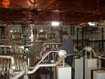
One of the oldest applications for antenna tuners is in mediumwave and shortwave AM broadcasting transmitters. AM band transmitters usually use a vertical antenna (tower) which are usually between 0.20 and 0.68 wavelengths long. At the base of the tower (in the "coupling hut")[29] an ATU is used to match the antenna to the 50 Ohm transmission line from the transmitter. The most commonly used circuit is a low-pass T-network with two series inductors and a shunt capacitor between them.
When multiple towers are used the ATU network may also provide for a phase adjustment, so that the currents in each tower can be phased relative to the others to produce a signal in a desired direction. Stations are often required by the terms of their operating license to prevent signals in directions that could produce interference with other stations. The transmitting station also benefits from more of the station's signal power, paid for in its electrical bill, going into its assigned target area, on which its advertising revenue is based. Adjustment of the ATUs in a multitower array is a complicated, time-consuming process, requiring considerable expertise.
High-power shortwave transmitters
High-power (50 kW and above) international shortwave broadcasting stations change frequencies seasonally – even daily – to adapt to ionospheric propagation conditions, so their signals can reach their intended audience. Frequent transmitting frequency changes require frequent adjustment of antenna matching and phasing circuitry. Modern shortwave transmitters typically include built-in impedance-matching circuitry for SWR up to 2:1 that can adjust to a new frequency and hence new output impedance within 15 seconds.
The matching networks in transmitters sometimes incorporate a balun or an external one can be installed at the transmitter in order to feed a balanced line. Through to the 1950s balanced transmission lines of 300 Ohms or more were more-or-less standard for all shortwave transmitters and antennas, even by amateurs. Most shortwave broadcasters continue to use high-impedance feeds even after automatic impedance matching has become commonly available.
The most commonly used shortwave antennas for international broadcasting are the HRS antenna (curtain array), which covers a 2 to 1 frequency range, and the log-periodic antenna, which can cover up to an 8 to 1 frequency range. Within the design range, the antenna SWR will vary, but these designs usually keep the SWR below 1.7 to 1 – easily within the range of SWR that can be tuned by built-in automatic antenna matching in many modern transmitters. So when feeding well-chosen antennas, a modern transmitter will be able to adjust itself as needed to match to the antenna at any frequency.
See also
Notes
- Transmitters with built-in antennas that only cover a narrow frequency band, such as cell phones and walkie-talkies, have an internal, non-user adjustable ATU circuit, permanently set to work with the installed antenna.
- Antenna and feedline impedance changes with the weather – especially if either is coated with dust, water from ice or rain, or is in humid air.
- Typical impedance transform ratios are 1:1, 1:4, 1:9, etc. The impedance ratio is the square of the winding ratio.
- When two differently-grounded cables or circuits must be connected but the grounds kept independent, a full, two-winding transformer with the desired ratio must be used, instead of a single-winding autotransformer.
- The same windings could be connected differently to make a balun instead.
- In general, a stub's change in reactance with changing frequency differs from the corresponding lumped component inductors and capacitors.
- To avoid high voltage at the end of an open stub, it is sometimes best to use the shorted stub between a quarter and a half wave in length for the capacitive stub. With low power applications, the open stub between a quarter and a half wave may be chosen for the inductive effect, as it is easier to trim for best match.
- The functional description of the components is roughly correct, but too simple. In actual operation, the inductor and all of the capacitors interact to produce the overall result.
- There is usually no benefit to forcing the two sides of an antenna to balance voltages. It is almost always better to allow the antenna to "float" with respect to an earth ground: Antenna performance that depends on balance always depends on balanced currents rather than balanced voltages, and forcing voltages to balance may unbalance currents.
- In the case of these circuits, it is almost always a bad idea to connect the equipment ground to the antenna ground, given the opportunity to keep the grounds separate. See[lower-alpha 9]
- Removing the optional ground on the balanced (right) side of the circuit does require the dual-section variable capacitor to be mounted so that it can electrically "float", with its frame and tuning shaft insulated from the chassis and tuning knob. When such insulated mounting is provided, there is no reason to use a dual-section capacitor and it can be replaced by a less expensive single-section capacitor.
- With the L-network, the loaded Q is not adjustable, but is fixed midway between the source and load impedances. Since most of the loss in practical tuners will be in the coil, changing from a low-pass to a high-pass circuit (or vice versa) might reduce the loss a little.
References
- "Load-pull for power devices". microwaves101.com.
- Stiles, Jim, Prof. (Spring 2009). "Matching with lumped elements" (PDF). Department of Electrical Engineering and Computer Science. EECS 723 – Microwave Engineering – course handouts. University of Kansas.
- Maxwell, Walter M. (1990). Reflections: Transmission lines and antennas (1st ed.). Newington, CT: American Radio Relay League. ISBN 0-87259-299-5.
- Moore, Cecil (9 January 2014). "Old XYL's tales in amateur radio".
- Silver, H. Ward, ed. (2011). ARRL Antenna Book. Newington, CT: American Radio Relay League. pp. 22–24. ISBN 978-0-87259-694-8.
- Cathey, T. (9 May 2009). "How to match a 50 Ohm coax to 75 Ohm coax, 35 Ohm Yagis, etc". AM Forum. amfone.net.
- The theoretical basis is discussion by the inventor, and wider application of the method for matching with 1⁄6-wave co-axial lines is found here: Branham, P. (1959). "A Convenient Transformer for matching Co-axial lines" (PDF). Geneva, CH: CERN.
- Storli, Martin (13 May 2017). "Single stub match calculator".
- Silver, H.L., ed. (2011). The ARRL Handbook for Radio Communications (88th ed.). Newington, CT: American Radio Relay League.
- Smith, Philip H. (1969). Electronic applications of the Smith Chart. Tucker, GA: Nobel Publishing. p. 121. ISBN 1-884932-39-8.
- "Drake MN-4 Users' Manual" (PDF). radiomanual.info. R. L. Drake Company.
- de Maw, Doug (W1FB) (1984). "Transmatch for balanced or unbalanced lines". In Hutchinson, Charles L. (ed.). The ARRL Handbook for the Radio Amateur (62nd ed.). Newington, CT: American Radio Relay League. Chapter 22 - Station setup and accessory projects: A transmatch for balanced or unbalanced lines, Figure 22.100. ISSN 0890-3565.
- McCoy, Lewis G. (W1ICP) (July 1970). "Ultimate transmatch". QST Magazine. Newington, CT: American Radio Relay League. pp. 24–27, 58.
- Silver, H. Ward, ed. (2011). ARRL Antenna Book. Newington, CT: American Radio Relay League. p. 24‑12. ISBN 978-0-87259-694-8.
- Salas, Phil. "A 100 Watt compact Z-match antenna tuner" (PDF).
- "Balanced line tuner".
- Hallas, Joel (1 September 2014). "The Doctor is In". QST. Newington, CT: American Radio Relay League. p. 60.
- Silver, H. Ward, ed. (2011). ARRL Antenna Book. Newington, Connecticut: American Radio Relay League. p. 24‑13. ISBN 978-0-87259-694-8.
- Miller, Dave (1 August 1995). "Back to Basics" (PDF). QST. Archived from the original (PDF) on 22 June 2013.
- HF Users’ Guide (PDF). SGC World.
- "Stealth Kit" (PDF). SGC World.
- "Smart tuners for stealth antennas" (PDF). SGC World.
- Hallas, Joel R., W1ZR (2010). The ARRL Guide to Antenna Tuners. Newington, CT: American Radio Relay League. p. 7‑4. ISBN 978-0-87259-098-4.
- Hallas, Joel R., W1ZR (2010). The ARRL Guide to Antenna Tuners. Newington, CT: American Radio Relay League. p. 4‑3. ISBN 978-0-87259-098-4.
- Silver, H. Ward, ed. (8 October 2014). The 2015 ARRL Handbook (92nd ed.). Newington, CT: American Radio Relay League. p. 20‑16. ISBN 978-1-62595-019-2.
- Schmidt, Kevin, W9CF. "Estimating T-network losses at 80 and 160 meters" (PDF). fermi.la.asu.edu.
- Stanley, J. (1 September 2015). "Antenna Tuners as Preselectors". Technical Correspondence. QST Magazine. p. 61.
- Hall, Jerry, ed. (1988). ARRL Antenna Book. Newington, CT: American Radio Relay League. p. 25‑18 ff. ISBN 978-0-87259-206-3.
- "Storm silences radio". The Sun (Sydney) (12379). New South Wales, Australia. 30 September 1949. p. 3. Retrieved 27 September 2019 – via National Library of Australia.
Further reading
- Wright, H. C. (1987). An Introduction to Antenna Theory. London: Bernard Babani. BP198.
- Radio Society of Great Britain (1976). The Radio Communication Handbook (5th ed.). Bedford, UK: Radio Society of Great Britain. ISBN 0-900612-58-4.
- Rohde, Ulrich L. (1974). "Die Anpassung von kurzen Stabantennen für KW-Sender" [Matching of short rod-antennas for short-wave transmitters]. Funkschau (in German) (7).
- Rohde, Ulrich L. (13 September 1975). "Match any antenna over the 1.5 to 30 MHz range with only two adjustable elements". Electronic Design. Vol. 19.