Loop antenna
A loop antenna is a radio antenna consisting of a loop or coil of wire, tubing, or other electrical conductor usually fed by a balanced source or feeding a balanced load. Within this physical description there are two distinct antenna types:
| Part of a series on |
| Antennas |
|---|
 |
The large self-resonant loop antenna has a circumference close to one wavelength of the operating frequency and so is resonant at that frequency. These antennas are used for both transmission and reception. Resonant loop antennas have a two-lobe radiation pattern; they are most sensitive to radio waves in two broad lobes in opposite directions, 180° apart.
Small loop antennas have a small circumference compared to the operating wavelength. They may be used for transmission and reception, although antennas that are very small compared to the wavelength are very inefficient radiators, and so are only used for reception. An example is the ferrite (loopstick) antenna used in most AM broadcast radios. The radiation pattern of a small loop antenna has two sharp nulls in opposite directions. Due to this directional pattern, small loops are used for radio direction finding (RDF), to locate the position of a transmitter.
Resonant loop antennas
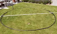
Resonant loop antennas are relatively large, governed by the intended wavelength of operation. They are mainly used at higher frequencies where their size is manageable. They can be viewed as a folded dipole split into an open shape. The loop's shape can be a circle, triangle, square, rectangle, or in fact any closed polygon; the only strict requirement is that its perimeter must be (slightly over) one full-wavelength.
The radiation pattern of a resonant loop antenna peaks at right angles to the plane of the loop. At the lower shortwave frequencies a full loop is physically quite large, and can practically only be installed "lying flat", with the plane of the loop horizontal to the ground, consisting of wires supported at the same height by masts at its corners.[1] This results in a radiation pattern peaking toward the vertical. Above 10 MHz, the loop is more frequently "standing up", that is with the plane of the loop vertical, in order to direct its main beam towards the horizon. It may be attached to an antenna rotator in order to rotate that direction as desired. Compared to a dipole or folded dipole, the large loop's radiation pattern is lower toward the sky or ground, giving it about 1.5 dB higher gain in the two favored horizontal directions.
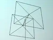
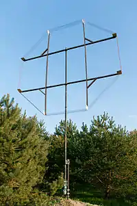
Additional gain (and a uni-directional radiation pattern) is usually obtained with an array of such elements either as a driven endfire array or in a Yagi configuration (with all but one loop being parasitic elements). The latter is widely used in amateur radio in the "quad" configuration (see photo).
Loop antennas may be in the shape of a circle, a square or any other closed geometric shape that allows the total perimeter to be one wavelength. The most popular shape in amateur radio is the quad antenna or "quad", a resonant loop in a square shape so that it can be constructed of wire strung across a supporting ‘X’ frame. There may be one or more additional loops stacked parallel to the first as parasitic elements, making the antenna system unidirectional with increased gain. This design can also be turned 45 degrees to a diamond shape supported on a ‘+’ frame. Triangular loops have also been used.[1] A rectangle twice as high as its width obtains slightly increased gain and also matches 50 ohms directly if used as a single element.[2]
The polarization of such an antenna is not obvious by looking at the loop itself, but depends on the feed point (where the transmission line is connected), and whether it is being operated as a 1, 2, or 3 wavelength loop. If a vertically oriented loop is fed at the bottom at its 1 wavelength frequency, it will be horizontally polarized; feeding it from the side will make it vertically polarized.
In all of the large loops described above, the antenna's operating frequency is assumed to be at its first resonance, whose corresponding wavelength almost matches the circumference of the loop.
Low frequency one wavelength loops "lying down" are sometimes used for NVIS operation. This is sometimes called a "lazy quad". It has a single lobe straight up. If fed on higher frequencies the circumference will be several wavelengths. Near the odd harmonics of the first resonant frequency, input resistance will be similar to that at the main resonance. At even harmonics the input resistance will be high. At other frequencies it will have a reactive part. Except at the odd harmonic frequencies, operation will require use of an antenna tuner. As the frequency increases, the pattern will break up into multiple lobes with peaks at lower angles. Since the higher frequency bands need lower angle lobes to propagate this can work to advantage.[3]
Small loops
Small loops (or magnetic loops) are “small” in comparison to their operating wavelength, typically between 5% and 30% of a wavelength in circumference. As with all antennas, antennas used much below resonance have a much smaller radiation resistance, increasing the relative importance of ohmic losses, resulting in a much poorer antenna efficiency. However, small loops may be resorted to at lower frequencies (wavelengths of tens to hundreds of meters) where resonant loops and half-wave dipole antennas become impractical.
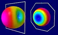
Contrary to resonant loop antennas, the antenna pattern of small loops peaks in the plane of the loop rather than broadside to it.
Small loops have advantages as receiving antennas at frequencies below 10 MHz.[4][5] Although a small loop's losses can be high, the receiving signal-to-noise ratio may not suffer at these lower frequencies, where received noise is dominated by atmospheric noise and static rather than receiver noise. The ability to rotate a smaller antenna may help to maximize the signal and reject interference.
Size, shape, efficiency, and pattern
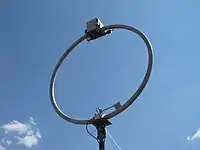
Small transmitting loops are “small” in comparison to a full-wave loop, but considerably larger than the small receiving loop, and unlike receiving loops must be “scaled-up” for longer wavelengths. They are typically used on frequencies between 3–30 MHz. They usually consist of a single turn of large diameter conductor, and are typically round or octagonal to provide maximum enclosed area for a given perimeter. The smaller of these loops are much less efficient than full-sized self-resonant loops,[6] but where space is at a premium the smaller loops can provide effective communications.[7][8] Loop antennas are relatively easy to build.[9]
A small transmitting loop antenna, also known as a magnetic loop, with a circumference 10% of a wavelength or less, will have a relatively constant current distribution along the conductor, and the main lobe will be in the plane of the loop. Loops of any size between 10% and 100% of a wavelength in circumference can be built and tuned to resonance with series reactance. A capacitor is required for a circumference less than a half wave, an inductor for loops more than a half wave and less than a full wave. Loops in this size range may have neither the uniform current of the small loop, nor the double peaked current of the full sized loop and thus cannot be analyzed using the concepts developed for the small receiving loops nor the self resonant loop antennas. Performance is best determined with NEC analysis. Antennas within this size range include the halo (see below) and the G0CWT (Edginton) loop.[10][11]
All small transmitting loops work even better for receiving.
Matching to the transmitter
In addition to other common impedance matching techniques such as a gamma match, transmitting loops are sometimes impedance matched by connecting the feedline to a smaller feed loop inside the area surrounded by the main loop.[8] Typical feed loops are 1⁄8 to 1⁄5 the size of the antenna's main loop. The combination is in effect a transformer, with power in the near-field inductively coupled from the feed loop to the main loop, which itself is connected to the resonating capacitor and is responsible for radiating most of the power.
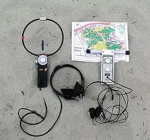
Use for land-mobile radio
Small loops are used in land-mobile radio (mostly military) at frequencies between 3–7 MHz, because of their ability to direct energy upwards, unlike a conventional whip antenna. This enables Near Vertical Incidence Skywave (NVIS) communication up to 300 km in mountainous regions. In this case a typical radiation efficiency of around 1% is acceptable because signal paths can be established with 1 Watt of radiated power or less when a transmitter generating 100 Watts is used.
In military use, the antenna may be built using a one or two conductors 1–2 inches in diameter. The loop itself is typically 6 feet in diameter.[12]
Power limits
One practical issue with small loops as transmitting antennas is that the loop not only has a very large current going through it, but also has a very high voltage across the capacitor, typically thousands of Volts when fed with only a few Watts of transmitter power. This requires a rather expensive and physically large resonating capacitor with a large breakdown voltage, in addition to having minimal dielectric loss (normally requiring an air-gap capacitor). In addition to making the geometric loop larger, efficiency may be increased by using larger conductors or other measures to reduce the conductor's loss resistance. However, lower loss means higher Q and even greater voltage on the capacitor.
This problem is more serious than with a vertical or dipole antenna that is short compared to a wavelength. There matching using a loading coil also generates a high voltage at the antenna end(s). However, unlike with capacitors, the voltage across a physically large inductor is generally not an issue.
Small receiving loops
If the perimeter of a loop antenna is much smaller than the wavelengths intended – say 1⁄3 to 1⁄100 of a wavelength – then the antenna is a small loop antenna. Several performance factors, including received power, scale in proportion to loop area. For a given loop area, the length of the conductor (and thus its net loss resistance) is minimized if the perimeter is circular, making a circle the optimal shape for small loops. Small receiving loops are typically used below 3 MHz where human-made and natural atmospheric noise dominate. Thus the signal-to-noise ratio of the received signal will not be adversely affected by low efficiency as long as the loop is not excessively small.
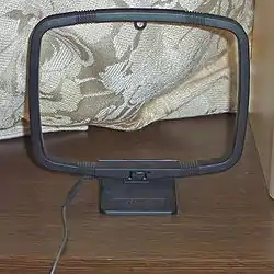
A typical diameter of receiving loops with "air centers" is between 30 cm and 1 meter. To increase the magnetic field in the loop and thus its efficiency, while greatly reducing size, the coil of wire is often wound around a ferrite rod magnetic core; this is called a ferrite loop antenna. Such ferrite loop antennas are used in almost all AM broadcast receivers with the exception of car radios; the antenna is then usually contained inside the radio's chassis. These antennas are also used for radio direction finding.[13]
The radiation resistance RR of a small loop is generally much smaller than the loss resistance RL due to the conductors composing the loop, leading to a poor antenna efficiency.[lower-alpha 1] Consequently, most of the power delivered to a small loop antenna will be converted to heat by the loss resistance, rather than doing useful work.
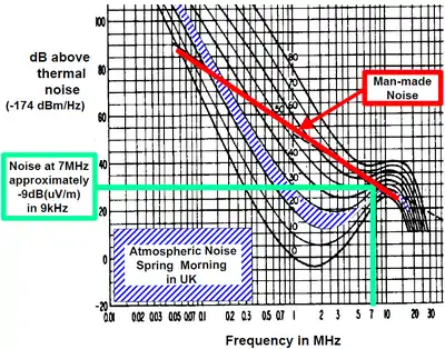
So much wasted power is not acceptable in a transmitting antenna, however in a receiving antenna the inefficiency is not important at frequencies below about 15 MHz. At these lower frequencies, atmospheric noise (static) and man-made noise (radio frequency interference) even in the weak signal from an inefficient antenna are far above the internal thermal or Johnson noise present in the radio receiver's circuits, so the weak signal from a loop antenna can be amplified without degrading the signal-to-noise ratio.[14]
For example, at 1 MHz the man-made noise might be 55 dB above the thermal noise floor. If a small loop antenna's loss is 50 dB (as if the antenna included a 50 dB attenuator) the electrical inefficiency of that antenna will have little influence on the receiving system's signal-to-noise ratio.
In contrast, at quieter frequencies at about 20 MHz and above, an antenna with a 50 dB loss could degrade the received signal-to-noise ratio by up to 50 dB, resulting in terrible performance.
Magnetic vs. electrical antennas
The small loop antenna is known as a magnetic loop since it behaves electrically as a coil (inductor). It couples to the magnetic field of the radio wave in the region near the antenna, in contrast to monopole and dipole antennas which couple to the electric field of the wave. In a receiving antenna (the main application of small loops) the oscillating magnetic field of the incoming radio wave induces a current in the wire winding by Faraday's law of induction.
Radiation pattern and polarization
Surprisingly, the radiation and receiving pattern of a small loop is quite opposite that of a large self resonant loop (whose circumference is close to one wavelength). Since the loop is much smaller than a wavelength, the current at any one moment is nearly constant round the circumference. By symmetry it can be seen that the voltages induced in the loop windings on opposite sides of the loop, will cancel each other when a perpendicular signal arrives on the loop axis. Therefore, there is a null in that direction.[15] Instead, the radiation pattern peaks in directions lying in the plane of the loop, because signals received from sources in that plane do not quite cancel owing to the phase difference between the arrival of the wave at the near side and far side of the loop. Increasing that phase difference by increasing the size of the loop has a large impact in increasing the radiation resistance and the resulting antenna efficiency.
Another way of looking at a small loop as an antenna is to consider it simply as an inductive coil coupling to the magnetic field in the direction perpendicular to plane of the coil, according to Ampère's law. Then consider a propagating radio wave also perpendicular to that plane. Since the magnetic (and electric) fields of an electromagnetic wave in free space are transverse (no component in the direction of propagation), it can be seen that this magnetic field and that of a small loop antenna will be at right angles, and thus not coupled. For the same reason, an electromagnetic wave propagating within the plane of the loop, with its magnetic field perpendicular to that plane, is coupled to the magnetic field of the coil. Since the transverse magnetic and electric fields of a propagating electromagnetic wave are at right angles, the electric field of such a wave is also in the plane of the loop, and thus the antenna's polarization (which is always specified as being the orientation of the electric, not the magnetic field) is said to be in that plane.
Thus mounting the loop in a horizontal plane will produce an omnidirectional antenna which is horizontally polarized; mounting the loop vertically yields a weakly directional antenna with vertical polarization and sharp nulls along the axis of the loop.[lower-alpha 2]
Receiver input tuning
Since a small loop antenna is essentially a coil, its electrical impedance is inductive, with an inductive reactance much greater than its radiation resistance. In order to couple to a transmitter or receiver, the inductive reactance is normally canceled with a parallel capacitance.[lower-alpha 3] Since a good loop antenna will have a high Q factor, this capacitor must be variable and is adjusted along with the receiver's tuning.
Small loop receiving antennas are also almost always resonated using a parallel plate capacitor, which makes their reception narrow-band, sensitive only to a very specific frequency. This allows the antenna, in conjunction with a (variable) tuning capacitor, to act as a tuned input stage to the receiver's front-end, in lieu of a preselector.
Insensitivity to locally generated interference
Due to its direct coupling to the magnetic field, unlike most other antenna types, the small loop is relatively insensitive to electric-field noise from nearby sources. No matter how close the electrical interference is to the loop, its effect will not be much greater than if it were a quarter wavelength away.[16] This is valuable since most sources of interference with radio frequency content, such as sparking at commutators or corona discharge, directly produce electric fields in the near-field (much less than a wavelength from the source). Since it is in the AM broadcast band and lower frequencies generally where these small loops are used, the near field region is physically quite large (on the order of 30 m, or 100 feet). This provides a considerable advantage for using an antenna which is relatively insensitive to the main interference sources encountered in that frequency range.
The same principle makes a small loop particularly sensitive to sources of magnetic noise in its near field. Likewise, a Hertzian (short) dipole couples directly with the electric field and is relatively immune to locally produced magnetic noise. However at radio frequencies nearby sources of magnetic interference are generally not an issue. In either case the small antenna's immunity does not extend to noise sources outside of the near field: Noise sources over one wavelength distant, whether originating as an electric or magnetic field, are received simply as electromagnetic waves. Noise from outside any antenna's near field will be received equally well by any antenna sensitive to a radio transmitter from the direction of that noise source.
Direction finding with small loops
Since the directional response of small loop antennas includes a sharp null in the direction normal to the plane of the loop, they are used in radio direction finding at longer wavelengths.
The procedure is to rotate the loop antenna to find the direction where the signal vanishes – the “null” direction. Since the null occurs at two opposite directions along the axis of the loop, other means must be employed to determine which side of the antenna the “nulled” signal is on. One method is to rely on a second loop antenna located at a second location, or to move the receiver to that other location, thus relying on triangulation.
Instead of triangulation, a second dipole or vertical antenna can be electrically combined with a loop or a loopstick antenna. Called a sense antenna, connecting and matching the second antenna changes the combined radiation pattern to a cardioid, with a null in only one (less precise) direction. The general direction of the transmitter can be determined using the sense antenna, and then disconnecting the sense antenna returns the sharp nulls in the loop antenna pattern, allowing a precise bearing to be determined.
AM broadcast receiving antennas
Small loop antennas are lossy and inefficient for transmitting, but they can be practical receiving antennas for frequencies below 10 MHz. Especially in the mediumwave (520–1710 kHz) band and below, where wavelength-sized antennas are infeasibly large, and the antenna inefficiency is irrelevant, due to large amounts of atmospheric noise.
AM broadcast receivers (and other low frequency radios for the consumer market) typically use small loop antennas, even when a telescoping antenna may be attached for FM reception.[17] A variable capacitor connected across the loop forms a resonant circuit that also tunes the receiver's input stage as that capacitor tracks the main tuning. A multiband receiver may contain tap points along the loop winding in order to tune the loop antenna at widely different frequencies.
In AM radios built prior to the discovery of ferrite in the mid-20th century, the antenna might consist of dozens of turns of wire mounted on the back wall of the radio – a planar helical antenna – or a separate, rotatable, furniture-sized rack looped with wire – a frame antenna.
Ferrite
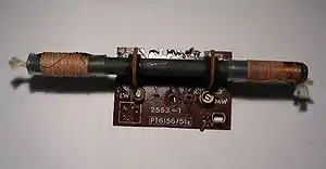
Ferrite loop antennas are made by winding fine wire around a ferrite rod. They are almost universally used in AM broadcast receivers.[18][lower-alpha 4] Other names for this type of antenna are loopstick, ferrite rod antenna or aerial, ferroceptor, or ferrod antenna. Often at shortwave frequencies Litz wire is used for the winding to reduce skin effect losses. Elaborate “basket weave” patterns are used at all frequencies to reduce self-capacitance in the coil and raise the loop self-resonance above the operating frequency, consequently improving the loop Q factor.
The ferrite increases the magnetic permeability and acts as a low-loss magnetic conductor – much better than air. This greater conductance channels thousands of times more magnetic power through the rod, and hence through the loop, allowing the physically small antenna to have a larger effective area.[19][20]
Loop-like antennas
Some antennas look very much like loops, but are either not continuous loops, or are designed to couple with the inductive near-field – over distances of a meter or two – rather than to transmit or receive long-distance electromagnetic waves in the radiative far-field.
Halo antennas
Although it has a superficially similar appearance, the so-called halo antenna is not technically a loop since it possesses a break in the conductor opposite the feed point; that totally changes the current pattern since the voltages across the break are opposite and large. It is better analyzed as a dipole (which also has a large voltage and zero current at the ends) which has been bent into a circle.
RFID coils
Strictly speaking, RFID tags and readers interact by induction rather than transmission waves, and so are not antennas. The use of coupling coils for inductive (magnetic) transmission systems including LF and HF (rather than UHF) is outside the scope of this article.
These systems do operate at radio frequencies, and do involve the use of small loops which are called "antennas" in the trade. Although these small loops are sometimes indistinguishable from the small loop antennas discussed here, such systems are not designed to transmit or receive signal waves (electromagnetic waves), and can only operate over short distances. They are near field systems involving alternating magnetic fields, and may be analyzed as poorly coupled transformer windings; their performance criteria are dissimilar to radio antennas as discussed here.
Footnotes
- The loss resistance includes not only the DC resistance of the conductor but also its increase due to the skin effect and proximity effect. The loss resistance also includes losses in the ferrite rod if one is used.
- Since AM broadcast radio is conventionally vertically polarized, the internal antennas of AM radios are loops in the vertical plane (that is, with the loopstick core, around which the loop is wound, horizontally oriented). One can easily demonstrate the directivity of such an antenna by tuning to an AM station (preferably a weaker one) and rotating the radio in all horizontal directions. At a particular orientation (and at 180 degrees from it) the station will be in the direction of the ‘null’, that is, in the direction of the loopstick (normal to the loop). At that point reception of the station will fade out.
- Although a series capacitor can likewise be used to cancel the reactive impedance, doing so results in the receiver (or transmitter) seeing a very small (resistive) impedance. A parallel resonance, on the other hand, leads to a very large impedance seen at the feedpoint when the capacitor's susceptance cancels that of the antenna, and thus an increased voltage which can directly be applied to a receiver's input stage.
- An important execption is that radios built for installation inside metal car bodies cannot contain antennas, since their reception would be blocked by of the metal of the chassis and the dashboard. Car radios must use external antennas, which are essentially never ferrite loops.
References
- Silver, H. Ward, ed. (2015). "Chapter 5 - Loop Antennas". The ARRL Antenna Book. Newington, CT: The American Radio Relay League, Inc. ISBN 978-1-62595-044-4.
- Silver 2015, Section 9.6.2
- https://www.dj0ip.de/my-favorite-antennas/my-favorite-all-band/
- "Magnetic receiving loops". w8ji.com.
- Rick Karlquist (17 Oct 2008). "Low Band Receiving Loops" (PDF). n6rk.com. PacifiCon presentation. Retrieved 2018-04-29.
- Kai Siwiak, KE4PT. "How efficient is your loop antenna?" (PDF). qsl.net.
- Brogdon, A. (Apr 2007). Low Profile Amateur Radio: Operating a ham station from almost anywhere (2nd ed.). Newington, CT: American Radio Relay League. ISBN 9780872599741.
- "Loop Antennas" (PDF).
- "A Great Shortwave Loop".
- "Practical Detail". www.g0cwt.co.uk.
- "WB5WPA main page". www.qsl.net.
- "Comrod communication". army-technology.com.
- Poole, Ian (2003). Newnes guide to radio and communications technology. Elsevier. pp. 113–114. ISBN 0-7506-5612-3.
- CCIR 258; CCIR 322.
- Rudge, A.W.; Milne, K.; Olver, A.D.; Knight, P. (1982). Handbook of Antenna Design. 2. p. 688. ISBN 978-0863415692.
- Rauch, Tom. "Small Magnetic Receiving Loops". W8JI.com.
- Dean, Charles E. (1959). Keith Henney (ed.). Radio Engineering Handbook. New York: McGraw-Hill. ch. 19 p. 21.
- Dean 1959, p. 23
- Graf, Rudolf F. (1999). Modern Dictionary of Electronics. Newnes. p. 278.
- Snelling, E.C. (1988). Soft Ferrites: Properties and applications (second ed.). Butterworths. p. 303. ISBN 0-408-02760-6.
External links
- Small Transmitting Loop Antenna Calculator - Online calculator that performs the "Basic Equations for a Small Loop" in The ARRL Antenna Book, 15th Edition
- Small Transmitting Loop Antennas - AA5TB