Collet
A collet /ˈkɒlɪt/ is a subtype of chuck that forms a collar around an object to be held and exerts a strong clamping force on the object when it is tightened, usually by means of a tapered outer collar. It may be used to hold a workpiece or a tool.
An external collet is a sleeve with a (normally) cylindrical inner surface and a conical outer surface. The collet can be squeezed against a matching taper such that its inner surface contracts to a slightly smaller diameter, squeezing the tool or workpiece to hold it securely. Most often this is achieved with a spring collet, made of spring steel, with one or more kerf cuts along its length to allow it to expand and contract. An alternative collet design is one that has several tapered steel blocks (essentially tapered gauge blocks) held in circular position (like the points of a star, or indeed the jaws of a jawed chuck) by a flexible binding medium (typically synthetic or natural rubber). Regardless of the collet design, the operating principle is the same: squeeze the collet against the tool or workpiece to be held, resulting in high static friction and accurate alignment.
An internal collet can be used to lock two telescoping tubes together. In this case the collet is in the form of a truncated cone drilled and threaded down the centreline. The collet diameter matches the bore of the inner tube, having the larger end slightly greater than the bore while the smaller diameter is slightly less than the bore. A threaded stud, anchored at its other end to the tube, is then used to pull the collet into the tube. The increasing diameter of the collet forces the inner tube to expand and be pushed against the inner wall of the outer tube thus locking the two tubes together. The inner tube is often slotted to facilitate this expansion.
Nomenclature
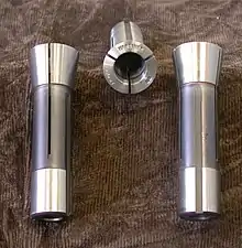
Generally, a collet chuck, considered as a unit, consists of a tapered receiving sleeve (sometimes integral with the machine spindle), the collet proper (usually made of spring steel) which is inserted into the receiving sleeve, and (often) a cap that screws over the collet, clamping it via another taper.
Usually in shop-floor terminology, the terms collet and chuck are used in contradistinction; users speak of holding a workpiece or tool with either a collet or a chuck. In this context "chuck" means any type of chuck other than a collet chuck (scroll chuck, independent-jaw chuck, etc.).
General features
Collets have a narrow clamping range and a large number of collets are required to hold a given range of bits. This gives the disadvantage of higher capital cost and makes them unsuitable for general usage in electric drills, etc. However, the collet's advantage over other types of chuck is that it combines all of the following traits into one chuck; making it highly useful for repetitive work:
| - | Collet | Scroll chuck | Independent-jaw chuck |
|---|---|---|---|
| 1. Fast chucking (unclamp one part, switch to a new part, reclamp) | Reliably | Reliably | Generally not |
| 2. Self centering | Reliably | Reliably | Never |
| 3. Strong clamping | Reliably | Usually | Reliably |
| 4. Resistance against being jarred loose (untightened) | Reliably | To varying extents | Usually |
| 5. Precise centering (run-out less than 0.005 in (0.13 mm) TIR and usually less than 0.001 in (0.025 mm)) | Reliably | Not reliably | Reliably (but requires time and skill) |
Of the above traits, scroll chucks offer always № 1 and № 2; usually № 3; to varying extents № 4 (depending on the situation); but not reliably № 5. Independent-jaw chucks offer always № 3; usually № 4; reliably № 5 (but at the expense of paying a skilled user to spend time achieving it); never № 2; and generally not № 1. Meanwhile, a collet chuck can deliver all reliably, and with no need for a skilled user (№s 3 to 5 do depend on the object being clamped closely matching the size and shape of the collet's clamping surface. This constraint is usually not a problem when the object is good-quality bar stock; the shank of a well maintained drill bit, reamer, end mill, etc.; or a previously machined part that is being rechucked for additional cutting operations).
Practical applications
Woodwork
On a wood router (a hand-held or table-mounted power tool used in woodworking), the collet is what holds the bit in place. In the U.S. it is generally for 0.25 or 0.5 inches (6.4 or 12.7 mm) bits, while in Europe bits are most commonly 6 or 8 mm (0.24 or 0.31 in). The collet nut is hexagonal on the outside so it can be tightened or loosened with a standard wrench, and has threads on the inside so it can be screwed onto the motor arbor.
Metalworking
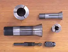
There are many types of collet used in the metalworking industry. Common industry-standard designs are R8[1] (internally threaded for mills) and 5C[2] (usually externally threaded for lathes). There are also proprietary designs which only fit one manufacturer's equipment. Collets can range in holding capacity from zero to several inches in diameter. The most common type of collet grips a round bar or tool, but there are collets for square, hexagonal, and other shapes. In addition to the outside-holding collets, there are collets used for holding a part on its inside surface so that it can be machined on the outside surface (similar to an expanding mandrel). Furthermore, it is not uncommon for machinists to make a custom collet to hold any unusual size or shape of part. These are often called emergency collets (e-collets) or soft collets (from the fact that they are bought in a soft (unhardened) state and machined as needed). Yet another type of collet is a step collet which steps up to a larger diameter from the spindle and allows holding of larger workpieces.
In use, the part to be held is inserted into the collet and then the collet is pressed (using a threaded nose cap) or drawn (using a threaded drawbar) into the body which has a conjugate taper form. The taper geometry serves to translate a portion of the axial drawing force into a radial clamping force. When properly tightened, enough force is applied to securely clamp the workpiece or tool. The cap or drawbar threads act as a screw lever, and this leverage is compounded by the taper, such that a modest torque on the screw produces an enormous clamping force.
The precise, symmetric form and rigid material of the collet provide precise, repeatable radial centering and axial concentricity. The basic mechanism fixes four of the six degrees of kinematic freedom, two locations and two angles. Collets may also be fitted to precisely align parts in the axial direction (a fifth degree of freedom) with an adjustable internal stop or by a shoulder stop machined into the internal form. The remaining sixth degree of freedom, namely the rotation of the part in the collet, may be fixed by using square, hexagonal, or other non-circular part geometry.
ER collets
The "ER" collet system, developed and patented by Rego-Fix in 1973, and standardized as DIN 6499, is the most widely used clamping system in the world and today available from many producers worldwide.[3][4] The standard series are: ER-8, ER-11, ER-16, ER-20, ER-25, ER-32, ER-40, and ER-50. The "ER" name came from an existing "E" collet (which were a letter series of names) which Rego-Fix modified and appended "R" for "Rego-Fix". The series number is the opening diameter of the tapered receptacle, in millimetres. ER collets collapse to hold parts up to 1mm smaller than the nominal collet internal size in most of the series (up to 2mm smaller in ER-50, and 0.5mm in smaller sizes) and are available in 1mm or 0.5mm steps. Thus a given collet holds any diameter ranging from its nominal size to its 1mm-smaller collapsed size, and a full set of ER collets in nominal 1mm steps fits any possible cylindrical diameter within the capacity of the series. With an ER fixture chuck, ER collets may also serve as workholding fixtures for small parts, in addition to their usual application as toolholders with spindle chucks.[5] Although a metric standard, ER collets with internal inch sizes are widely available for convenient use of imperial sized tooling. The spring geometry of the ER collet is well-suited only to cylindrical parts, and not typically applied to square or hexagonal forms like 5C collets.
Autolock collets
"Autolock" collet chucks (Osbourn "Pozi-Lock" is a similar system) were designed to provide secure clamping of milling cutters with only hand tightening. They were developed in the 1940s by a now defunct UK company, Clarkson (Engineers) Limited, and are commonly known as Clarkson chucks. Autolock collets require cutters with threaded shank ends to screw into the collet itself. Any rotation of the cutter forces the collet against the collet cap taper which tightly clamps the cutter, the screw fitting also prevents any tendency of the cutter to pull out. Collets are only available in fixed sizes, imperial or metric, and the cutter shank must be an exact match.[6]
The tightening sequence of Autolock collets is widely misunderstood. The chuck cap itself does not tighten the collet at all, with the cap tight and no tool inserted the collet is loose in the chuck. Only when a cutter is inserted will the collet be pressed against the cap taper. The back of the cutter engages with a centering pin and further turning drives the collet against the chuck cap, tightening around the cutter shank, hence "Autolock".
The correct installation sequence as per the original specification is:
- Insert the collet and hand tighten the chuck cap (collet free to float)
- Insert the tool and hand tighten (tool engaged with rear pin and collet engaging cap taper)
As the tool is used further rotation tightens the collet and the centering pin ensures that tool extension and alignment remain unchanged. A spanner is only required to release the locked collet.[7]
While threaded shank "Autolock" tools may be gripped by plain collets, such as ER, plain shank tools should never be used in an "Autolock" collet as they will not be properly clamped or aligned.
R8 collets
R8 collets were developed by Bridgeport Machines, Inc. for use in milling machines. Unusually, R8 collets fit into the machine taper itself (i.e. there is no separate chuck) and tools with integral R8 taper can also be directly fitted. R8 was developed to allow rapid tool changes and requires an exact match between collet and tool shank diameter.
R8 collets have a keyway to prevent rotation when fitting or removing, but it is the compressed taper and not the keyway that provides the driving force. Collets are compressed by a drawbar from behind, they are self releasing and tool changes can be automated.
5C collets
Unlike most other machine collet systems, 5C collets were developed primarily for work holding. Superficially similar to R8 collets, 5C collets have an external thread at the rear for drawing the collet closed and so work pieces may pass right through the collet and chuck (5C collets often also have an internal thread for workpiece locating). Collets are also available to hold square and hex stock. 5C collets have a limited closing range, and so shank and collet diameters must be a close match. A number of other C-series collets (1C, 3C, 4C, 5C, 16C, 20C & 25C) with different holding ranges also exist.
A collet system with capabilities similar to the 5C (originally a proprietary system of Hardinge) is the 2J (originally a proprietary system of Sjogren, a competitor of Hardinge, and which Hardinge later assimilated).
355E Collets
The SO Deckel tool grinders use these. Sometimes called U2 collets.
Watchmaker collets
Watchmaking at Waltham led to the invention of collets. Watchmakers' lathes all take collets which are sized by their external thread. The most popular size is 8 mm which came in several variations but all 8 mm collets are interchangeable. Lorch, a German Lathe maker, started with 6 mm collets and the first Boleys used a 6.5 mm collet. 6 mm collets will fit into a 6.5 mm lathe but it is a poor practice. Another popular size is the 10 mm collet used by Clement and Levin. For work holding, collets are sized in 0.1 mm increments with the number on the face being the diameter in tenths of a millimetre. Thus a 5 is a 0.5 mm collet.
Watchmaker collets come in additional configurations. There are step collets which step inward to hold gear wheels by the outer perimeter. These typically were made in sets of five to accommodate a range of different size gear wheels. These, like straight rod-holding collets, close on the outer taper. Ring collets also come in sets of five and hold work from inside a hole. They open as they are tightened by an outside taper against the outer taper of the lathe headstock.
Watch collets also include taper adapters and wax or cement chucks. These collets take an insert, usually brass, to which small parts are cemented, usually with shellac.
An excellent source is [8] This book has tables of makers and size but refers to the basic collets as "split wire chucks."
DIN 6343 dead length collets
These collets are common especially on production machines, particularly European lathes with lever or automated closers. Unlike draw-in collets, they do not pull back to close, but are generally pushed forward, with the face remaining in place.
Multi-size collets
Collets allowing a wider range of workholding by means of springs or elastic spacers between jaws; such collets were developed by Jacobs (Rubberflex), Crawford (Multibore), and Pratt Burnerd, and are in some cases compatible with certain spring collet chucks.
Morse taper collets
Although Morse tapers are intended to hold tools or tool holders (chucks & arbors), collets are also available. These can be used to hold tools with better accuracy (less run-out) than a chuck.
Craft hobbies
Many users (hobbyists, graphic artists, architects, students, and others) may be familiar with collets as the part of an X-Acto or equivalent knife that holds the blade. Another common example is the collet that holds the bits of a Dremel or equivalent rotary file.
Semiconductor work
In semiconductor industry, a die collet is used for picking a die up from a wafer after die cutting process has finished, and bonding it into a package. Some of them are made with rubber, and use vacuum for picking.
Internal combustion engines
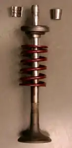
Most internal combustion engines use a split collet to hold both the inlet and exhaust valves under constant valve spring pressure which returns the valves to their closed position when the camshaft lobes are not in contact with the top of the valves. The two collet halves have an internal raised rib which locate into a circular groove near the top of each valve stem, the outer side of the collet halves are a taper fit into the spring retainer (also known as a collar), this taper locks the retainer in place and the raised rib that sits in the circular groove on the valve stem also locks the collet halves in place to the valve stem. To remove the valves from a cylinder head a 'valve spring compressor' is used to compress the valve springs by exerting force on the spring retainer which allows the collets to be removed, when the compressor is removed, the retainer, spring and valve can then be removed from the cylinder head. It may be realized that the retainer does not budge when the valve spring compressor is used, this is due to a buildup of carbon which over time has locked the retainer and collets slightly. A slight sharp tap on the backside of the valve spring compressor above the valve stem should free the retainer allowing the springs to be compressed whilst retrieving the split collet. On reassembly it is difficult to keep the split collets in place whilst the compressor is released, by applying a small amount of grease to the internal side of the split collets will keep them in place on the valve stem whilst releasing the compressor, then as the spring retainer rises it locks the tapered split collets in place.
See also
References
- Smid, Peter (2010). CNC Control Setup for Milling and Turning: Mastering CNC Control Systems. ISBN 9780831133504.
- Hoffman 2004, p. 275.
- "Archived copy". Archived from the original on 2012-09-22. Retrieved 2012-09-12.CS1 maint: archived copy as title (link)
- Machinery's Handbook 28th edition. 2008. p. 947.
- http://www.rego-fix.com/catalog/pdfs/14_Technical.pdf Archived December 27, 2014, at the Wayback Machine
- http://www.flightglobal.com/FlightPDFArchive/1942/1942%20-%201815.PDF
- http://www.flightglobal.com/FlightPDFArchive/1942/1942%20-%201815.PDF
- The Modern Watchmakers Lathe and How to use it by Archie Perkins. ISBN 0-918845-23-8
Bibliography
- Hoffman, Edward G. (2004), Jig and fixture design (5th ed.), Cengage Learning, ISBN 978-1-4018-1107-5.
External links
| Wikimedia Commons has media related to Collet chucks. |