Hobbing
Hobbing is a machining process for gear cutting, cutting splines, and cutting sprockets on a hobbing machine, which is a special type of milling machine. The teeth or splines of the gear are progressively cut into the material (a flat, cylindrical piece of metal) by a series of cuts made by a cutting tool called a hob. Compared to other gear forming processes it is relatively inexpensive but still quite accurate, thus it is used for a broad range of parts and quantities.[1]
It is the most widely used gear cutting process for creating spur and helical gears[2] and more gears are cut by hobbing than any other process as it is relatively quick and inexpensive.[3]
A type of skiving that is analogous to the hobbing of external gears can be applied to the cutting of internal gears, which are skived with a rotary cutter (rather than shaped or broached).[4]
Process


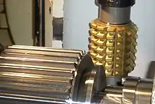
Hobbing uses a hobbing machine with two skew spindles, one mounted with a blank workpiece and the other with the hob. The angle between the hob's spindle (axis) and the workpiece's spindle varies, depending on the type of product being produced. For example, if a spur gear is being produced, then the hob is angled equal to the lead angle of the hob; if a helical gear is being produced then the angle must be increased by the same amount as the helix angle of the helical gear. The hobbing features for gears are straight, helical, straight bevel, face, crowned, worm, cylkro and chamfering. [5] The two shafts are rotated at a proportional ratio, which determines the number of teeth on the blank; for example, for a single-threaded hob if the gear ratio is 40:1 the hob rotates 40 times to each turn of the blank, which produces 40 teeth in the blank. If the hob has multiple threads the speed ratio must be multiplied by the number of threads on the hob.[6] The hob is then fed up into the workpiece until the correct tooth depth is obtained. Finally the hob is fed through the workpiece parallel to the blank's axis of rotation.[5]
Often multiple blanks are stacked, then cut in one operation.[6]
For very large gears the blank can be gashed to the rough shape first to make hobbing easier.
Equipment
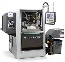
Hobbing machines, also known as hobbers, are fully automated machines that come in many sizes, because they need to be able to produce anything from tiny instrument gears up to 10 ft (3.0 m) diameter marine gears. Each gear hobbing machine typically consists of a chuck and tailstock, to hold the workpiece or a spindle, a spindle on which the hob is mounted, and a drive motor.[3]
For a tooth profile which is a theoretical involute, the fundamental rack is straight-sided, with sides inclined at the pressure angle of the tooth form, with flat top and bottom. The necessary addendum correction to allow the use of small-numbered pinions can either be obtained by suitable modification of this rack to a cycloidal form at the tips, or by hobbing at other than the theoretical pitch circle diameter. Since the gear ratio between hob and blank is fixed, the resulting gear will have the correct pitch on the pitch circle, but the tooth thickness will not be equal to the space width.
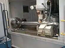
Hobbing machines are characterised by the largest module or pitch diameter it can generate. For example, a 10 in (250 mm) capacity machine can generate gears with a 10 in pitch diameter and usually a maximum of a 10 in face width. Most hobbing machines are vertical hobbers, which means the blank is mounted vertically. Horizontal hobbing machines are usually used for cutting longer workpieces; i.e. cutting splines on the end of a shaft.[7]
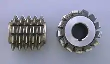
Hob
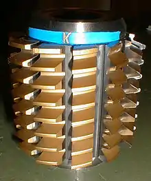
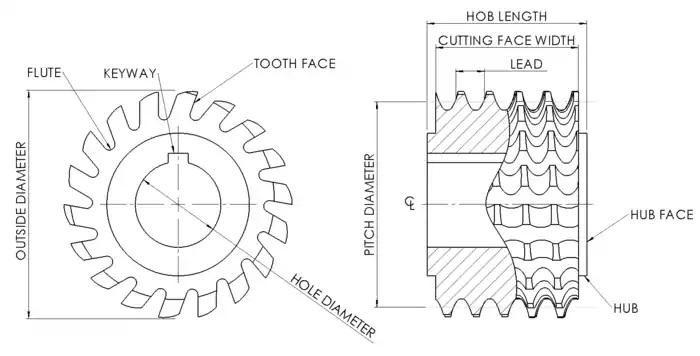
The hob is a cutting tool used to cut the teeth into the workpiece. It is cylindrical in shape with helical cutting teeth. These teeth have grooves that run the length of the hob, which aid in cutting and chip removal. There are also special hobs designed for special gears such as the spline and sprocket gears.[3]
The cross-sectional shape of the hob teeth are almost the same shape as teeth of a rack gear that would be used with the finished product. There are slight changes to the shape for generating purposes, such as extending the hob's tooth length to create a clearance in the gear's roots.[8] Each hob tooth is relieved on the back side to reduce friction.[9]
Most hobs are single-thread hobs, but double-, and triple-thread hobs increase production rates. The downside is that they are not as accurate as single-thread hobs.[10] Depending on type of gear teeth to be cut, there are custom made hobs and general purpose hobs. Custom made hobs are different from other hobs as they are suited to make gears with modified tooth profiles. The tooth profile is modified to add strength and reduce size and gear noise.
This list outlines types of hobs:
- Roller chain sprocket hobs
- Worm wheel hobs
- Spline hobs
- Chamfer hobs
- Spur and helical gear hobs
- Straight side spline hobs
- Involute spline hobs
- Serration hobs
- Semitopping gear hobs
Uses
Hobbing is used to make the following types of finished gears:
- Cycloid gears (see below)
- Helical gears
- Involute gears
- Ratchets
- Splines
- Sprockets
- Spur gears
- Worm gears
Hobbing is used to produce most throated worm wheels, but certain tooth profiles cannot be hobbed. If any portion of the hob profile is perpendicular to the axis then it will have no cutting clearance generated by the usual backing off process, and it will not cut well.
Cycloidal forms
For cycloidal gears (as used in BS978-2 Specification for fine pitch gears) and cycloidal-type gears each module, ratio and number of teeth in the pinion requires a different hobbing cutter, so the technique is only suitable for large volume production.
To circumvent this problem a special war-time emergency circular arc gear standard was produced giving a series of close-to-cycloidal forms which could be cut with a single hob for each module for eight teeth and upwards to economize on cutter manufacturing resources. A variant on this is still included in BS978-2a (Gears for instruments and clockwork mechanisms. Cycloidal type gears. Double circular arc type gears).
Tolerances of concentricity of the hob limit the lower modules which can be cut practically by hobbing to about 0.5 module.
History
Christian Schiele of Lancaster England, patented the hobbing machine in 1856.[11] It was a simple machine, but the rudimentary parts are present in the customary patent drawings. The hob cutting tool and the gear train to provide the appropriate ratio are clearly visible. Knowledge of hobbing probably precedes his patent likely within the watchmaking trades. The Antikythera mechanism (70–60 BC) is still being studied and is yielding more information [12]about how it was produced. While not a clock, it is clear that many gears with large tooth counts as high as 354 in complex gear trains exist in this astronomical instrument.[13] The maker(s) of the Antikythera mechanism are unknown, the tools and shop location are lost to time.
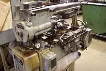
Many manufacturing firms that maintain museums of how products were produced in times past will have examples of manual gear hobs that helped to produce gears prior to the gears of the 19th century and earlier. Along with these completely manual gear hobs will be samples of some of the first semi-automated gear hobs, and finally examples of more recent technology that demonstrates the fully automated process that modern gear hobs use to produce gears today. A few producers of gear hobs also have interesting literature on the history of gear hobs, including details about how modern gear hobs can produce thousands of gears in a single hour.
See also
References
- American Society for Metals, Cubberly & Bardes 1978, p. 334.
- Drozda et al. 1983, p. 13‐34.
- Todd, Allen & Alting 1994, pp. 59–60.
- Weppelmann, E; Brogni, J (March 2014), "A breakthrough in power skiving", Gear Production: A Supplement to Modern Machine Shop: 7–12, retrieved 2014-03-11.
- Degarmo, Black & Kohser 2003, p. 769.
- Jones 1964, p. 289.
- Endoy 1990, p. 6.
- Jones 1964, p. 288.
- Degarmo, Black & Kohser 2003, p. 768.
- Degarmo, Black & Kohser 2003, p. 770.
- "The Original Hobbing Machine". Evolvent Design. Retrieved 2021-01-17.
- "Antikythera Mechanism : British Horological Institute". bhi.co.uk. Retrieved 2021-01-17.
- "The Antikythera Mechanism Episode 1 - Greeks, Clocks and Rockets. - YouTube". www.youtube.com. Retrieved 2021-01-17.
Bibliography
- American Society for Metals; Cubberly, William H.; Bardes, Bruce P. (1978), Metals Handbook: Machining, 16 (9th, Illustrated ed.), ASM International, ISBN 978-0-87170-007-0.
- Degarmo, E. Paul; Black, J T.; Kohser, Ronald A. (2003), Materials and Processes in Manufacturing (9th ed.), Wiley, ISBN 0-471-65653-4.
- Drozda, Tom; Wick, Charles; Benedict, John T.; Veilleux, Raymond F.; Society of Manufacturing Engineers; Bakerjian, Ramon (1983), Tool and Manufacturing Engineers Handbook: Machining, 1 (4th, illustrated ed.), Society of Manufacturing Engineers, ISBN 978-0-87263-085-7.
- Endoy, Robert (1990), Gear hobbing, shaping, and shaving (Illustrated ed.), Society of Manufacturing Engineers, ISBN 978-0-87263-383-4.
- Jones, Franklin D. (1964), Machine Shop Training Course (5th, Illustrated ed.), Industrial Press Inc., ISBN 978-0-8311-1040-6.
- Todd, Robert H.; Allen, Dell K.; Alting, Leo (1994), Manufacturing Processes Reference Guide, Industrial Press Inc., ISBN 0-8311-3049-0.
Further reading
- Burstall, Aubrey F. (1965), A History of Mechanical Engineering, MIT Press, ISBN 0-262-52001-X, LCCN 65-10278. At p. 303, "The hobbing process conceived in 1856 by Christian Schiele became a practical one for production work as soon as involute-shaped gear teeth superseded the cycloidal type in the 1880s, since the involute hob, like the involute rack, has straight sides (for the worm is a form of continuous rack) so that to make a hob from a worm all one has to do is to gash some teeth in the worm so that it will cut the blank as it is rotated."
- GB 185702896, Schiele, Christian, "Machinery for Cutting Nuts, Screws, and Toothed Wheels", published 6 December 1856, issued 5 June 1857; pre-1890 patent not found at eSpaceNet (see British Library remarks); see Google Books reprint which is missing sheets 1 and 2. Complete drawing set can be found here [1]
- Woodbury, Robert S. (1958), History of the Gear-Cutting Machine: A Historical Study in Geometry and Machines, MIT Press, ISBN 9780262730013, OCLC 1689960. At p. 105, "But it had been recognized that the worm was a form of continuous rack and all that was necessary to cut gears with it was to provide cutting edges on it — to make a hob (Fig. 45). Teeth had been cut by this method probably for the first time by Ramsden in 1768."
- Woodbury, Robert S. (1972), "History of the Gear-Cutting Machine.", Studies in the History of Machine Tools, Cambridge, Massachusetts: MIT Press, ISBN 978-0-262-73033-4, LCCN 72006354, OCLC 609185
- Dudley, Darle W. (1969), "The Evolution of the Gear Art", Published by, American Gear Manufacturers Association, Washington D.C., Library of Congress Catalog Card Number: 72-78509
- Radzevich, Stephen P. (2017), "Gear cutting tools: science and engineering", CRC Press, Second Edition, ISBN 9781138037069. Chapter 1 provides a very comprehensive and contemporary history of Gear Cutting Tools in Chapter 1.
External links
- Gimpert, Dennis (January 1994), "The Gear Hobbing Process" (PDF), Gear Technology, 11 (1): 38–44. Has schematics of hobbing machines in figures 8–10.