Telegrapher's equations
The telegrapher's equations (or just telegraph equations) are a pair of coupled, linear partial differential equations that describe the voltage and current on an electrical transmission line with distance and time. The equations come from Oliver Heaviside who developed the transmission line model starting with an August 1876 paper, On the Extra Current.[1]:66–67 The model demonstrates that the electromagnetic waves can be reflected on the wire, and that wave patterns can form along the line.
The theory applies to transmission lines of all frequencies including direct current and high-frequency. Originally developed to describe telegraph wires, the theory can also be applied to radio frequency conductors, audio frequency (such as telephone lines), low frequency (such as power lines), and pulses of direct current. It can also be used to electrically model wire radio antennas as truncated single-conductor transmission lines.[2]:7–10 [3]:232
Distributed components
The telegrapher's equations, like all other equations describing electrical phenomena, result from Maxwell's equations. In a more practical approach, one assumes that the conductors are composed of an infinite series of two-port elementary components, each representing an infinitesimally short segment of the transmission line:
- The distributed resistance of the conductors is represented by a series resistor (expressed in ohms per unit length). In practical conductors, at higher frequencies, increases approximately proportional to the square root of frequency due to the skin effect.
- The distributed inductance (due to the magnetic field around the wires, self-inductance, etc.) is represented by a series inductor (henries per unit length).
- The capacitance between the two conductors is represented by a shunt capacitor C (farads per unit length).
- The conductance of the dielectric material separating the two conductors is represented by a shunt resistor between the signal wire and the return wire (siemens per unit length). This resistor in the model has a resistance of ohms. accounts for both bulk conductivity of the dielectric and dielectric loss. If the dielectric is an ideal vacuum, then .


The model consists of an infinite series of the infinitesimal elements shown in the figure, and that the values of the components are specified per unit length so the picture of the component can be misleading. An alternative notation is to use , , , and to emphasize that the values are derivatives with respect to length. These quantities can also be known as the primary line constants to distinguish from the secondary line constants derived from them, these being the characteristic impedance, the propagation constant, attenuation constant and phase constant. All these constants are constant with respect to time, voltage and current. They may be non-constant functions of frequency.


Role of different components
The role of the different components can be visualized based on the animation at right.
- The inductance L makes it look like the current has inertia—i.e. with a large inductance, it is difficult to increase or decrease the current flow at any given point. Large inductance makes the wave move more slowly, just as waves travel more slowly down a heavy rope than a light one. Large inductance also increases the wave impedance (lower current for the same voltage).
- The capacitance C controls how much the bunched-up electrons within each conductor repel the electrons in the other conductor. By absorbing some of these bunched up electrons, the speed of the wave and its strength (voltage) are both reduced. With a larger capacitance, there is less repulsion, because the other line (which always has the opposite charge) partly cancels out these repulsive forces within each conductor. Larger capacitance equals (weaker restoring force)s making the wave move slightly slower, and also gives the transmission line a lower impedance (higher current for the same voltage).
- R corresponds to resistance within each line, and G allows current to flow from one line to the other. The figure at right shows a lossless transmission line, where both R and G are 0.
Values of primary parameters for telephone cable
Representative parameter data for 24 gauge telephone polyethylene insulated cable (PIC) at 70 °F (294 K)
| Frequency | R | L | G | C | ||||
|---|---|---|---|---|---|---|---|---|
| Hz | Ω⁄km | Ω⁄1000 ft | mH⁄km | mH⁄1000 ft | µS⁄km | µS⁄1000 ft | nF⁄km | nF⁄1000 ft |
| 1 Hz | 172.24 | 52.50 | 0.6129 | 0.1868 | 0.000 | 0.000 | 51.57 | 15.72 |
| 1 kHz | 172.28 | 52.51 | 0.6125 | 0.1867 | 0.072 | 0.022 | 51.57 | 15.72 |
| 10 kHz | 172.70 | 52.64 | 0.6099 | 0.1859 | 0.531 | 0.162 | 51.57 | 15.72 |
| 100 kHz | 191.63 | 58.41 | 0.5807 | 0.1770 | 3.327 | 1.197 | 51.57 | 15.72 |
| 1 MHz | 463.59 | 141.30 | 0.5062 | 0.1543 | 29.111 | 8.873 | 51.57 | 15.72 |
| 2 MHz | 643.14 | 196.03 | 0.4862 | 0.1482 | 53.205 | 16.217 | 51.57 | 15.72 |
| 5 MHz | 999.41 | 304.62 | 0.4675 | 0.1425 | 118.074 | 35.989 | 51.57 | 15.72 |
More extensive tables and tables for other gauges, temperatures and types are available in Reeve.[4] Chen[5] gives the same data in a parameterized form that he states is usable up to 50 MHz.
The variation of and is mainly due to skin effect and proximity effect.
The constancy of the capacitance is a consequence of intentional, careful design.
The variation of G can be inferred from Terman: “The power factor ... tends to be independent of frequency, since the fraction of energy lost during each cycle ... is substantially independent of the number of cycles per second over wide frequency ranges.”[6] A function of the form with close to 1.0 would fit Terman’s statement. Chen [5] gives an equation of similar form.


G in this table can be modeled well with


Usually the resistive losses grow proportionately to and dielectric losses grow proportionately to with so at a high enough frequency, dielectric losses will exceed resistive losses. In practice, before that point is reached, a transmission line with a better dielectric is used. In long distance rigid coaxial cable, to get very low dielectric losses, the solid dielectric may be replaced by air with plastic spacers at intervals to keep the center conductor on axis.


The equations
The telegrapher's equations are:

They can be combined to get two partial differential equations, each with only one dependent variable, either or :


Except for the dependent variable ( or ) the formulas are identical.

General solution for terminated lines of finite length
Let

be the Fourier transform of the input voltage , then the general solutions for voltage and current are


and

with

being the transfer function of the line,

the series impedance, and

the shunt impedance. The parameter represents the total length of the line. is the impedance of the electrical termination. Without termination, is infinite.


Lossless transmission
When ωL >> R and ωC >> G, resistance can be neglected, and the transmission line is considered as an ideal lossless structure. In this case, the model depends only on the L and C elements. The Telegrapher's Equations then describe the relationship between the voltage V and the current I along the transmission line, each of which is a function of position x and time t:


The equations for lossless transmission lines
The equations themselves consist of a pair of coupled, first-order, partial differential equations. The first equation shows that the induced voltage is related to the time rate-of-change of the current through the cable inductance, while the second shows, similarly, that the current drawn by the cable capacitance is related to the time rate-of-change of the voltage.


The Telegrapher's Equations are developed in similar forms in the following references: Kraus,[7] Hayt,[8] Marshall,[9] Sadiku,[10] Harrington,[11] Karakash,[12] and Metzger.[13]
These equations may be combined to form two exact wave equations, one for voltage V, the other for current I:


where

is the propagation speed of waves traveling through the transmission line. For transmission lines made of parallel perfect conductors with vacuum between them, this speed is equal to the speed of light.
Sinusoidal steady-state
In the case of sinusoidal steady-state (i.e., when a pure sinusoidal voltage is applied and transients have ceased), the voltage and current take the form of single-tone sine waves:


where is the angular frequency of the steady-state wave. In this case, the Telegrapher's equations reduce to


Likewise, the wave equations reduce to


where k is the wave number:

Each of these two equations is in the form of the one-dimensional Helmholtz equation.
In the lossless case, it is possible to show that

and

where is a real quantity that may depend on frequency and is the characteristic impedance of the transmission line, which, for a lossless line is given by


and and are arbitrary constants of integration, which are determined by the two boundary conditions (one for each end of the transmission line).


This impedance does not change along the length of the line since L and C are constant at any point on the line, provided that the cross-sectional geometry of the line remains constant.
The lossless line and distortionless line are discussed in Sadiku,[14] and Marshall,[15]
General solution
The general solution of the wave equation for the voltage is the sum of a forward traveling wave and a backward traveling wave:

where
- and can be any functions whatsoever, and
- is the waveform's propagation speed (also known as phase velocity).


f1 represents a wave traveling from left to right in a positive x direction whilst f2 represents a wave traveling from right to left. It can be seen that the instantaneous voltage at any point x on the line is the sum of the voltages due to both waves.
Since the current I is related to the voltage V by the telegrapher's equations, we can write

Lossy transmission line
When the loss elements R and G are not negligible, the differential equations describing the elementary segment of line are

By differentiating both equations with respect to x, and some algebraic manipulation, we obtain a pair of hyperbolic partial differential equations each involving only one unknown:

These equations resemble the homogeneous wave equation with extra terms in V and I and their first derivatives. These extra terms cause the signal to decay and spread out with time and distance. If the transmission line is only slightly lossy (R ≪ ωL and G ≪ ωC ), signal strength will decay over distance as e−α x, where [16]:130

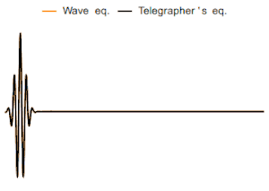
Signal pattern examples
Depending on the parameters of the telegraph equation, the changes of the signal level distribution along the length of the single-dimensional transmission medium may take the shape of the simple wave, wave with decrement, or the diffusion-like pattern of the telegraph equation. The shape of the diffusion-like pattern is caused by the effect of the shunt capacitance.
Antennas
Because the equations governing the flow of current in wire antennas are identical to the telegrapher's equations,[2]:7–10 [3]:232 antenna segments can be modeled as two-way, single-conductor transmission lines. The antenna is broken into multiple line segments, each segment having approximately constant primary line parameters, R, L, C, and G.[lower-alpha 1]
At the tip of the antenna, the transmission-line impedance is essentially infinite (equivalently, the admittance is almost zero) and after a brief "pile-up" at the tip, the wave reverses direction and flows back towards the feedpoint. The consequence is that the antenna wire carries waves from the feedpoint to the tip, and then from the tip, back to the feedpoint. The combination of the overlapping, oppositely-directed waves form the familiar standing waves most often considered for practical antenna-building. Further, partial reflections occur within the antenna where ever there is a mismatched impedance at the junction of two or more elements, and these reflected waves also contribute to standing waves along the length of the wire(s).[2][3]
Solutions of the telegrapher's equations as circuit components
The solutions of the telegrapher's equations can be inserted directly into a circuit as components. The circuit in the top figure implements the solutions of the telegrapher's equations.[17]
The bottom circuit is derived from the top circuit by source transformations.[18] It also implements the solutions of the telegrapher's equations.
The solution of the telegrapher's equations can be expressed as an ABCD type two-port network with the following defining equations[19]

The ABCD type two-port gives and as functions of and . Both of the circuits above, when solved for and as functions of and yield exactly the same equations.


In the bottom circuit, all voltages except the port voltages are with respect to ground and the differential amplifiers have unshown connections to ground. An example of a transmission line modeled by this circuit would be a balanced transmission line such as a telephone line. The impedances Z(s), the voltage dependent current sources (VDCSs) and the difference amplifiers (the triangle with the number "1") account for the interaction of the transmission line with the external circuit. The T(s) blocks account for delay, attenuation, dispersion and whatever happens to the signal in transit. One of the T(s) blocks carries the forward wave and the other carries the backward wave. The circuit, as depicted, is fully symmetric, although it is not drawn that way. The circuit depicted is equivalent to a transmission line connected from to in the sense that , , and would be same whether this circuit or an actual transmission line was connected between and . There is no implication that there are actually amplifiers inside the transmission line.

Every two-wire or balanced transmission line has an implicit (or in some cases explicit) third wire which may be called shield, sheath, common, Earth or ground. So every two-wire balanced transmission line has two modes which are nominally called the differential and common modes. The circuit shown on the bottom only models the differential mode.
In the top circuit, the voltage doublers, the difference amplifiers and impedances Z(s) account for the interaction of the transmission line with the external circuit. This circuit, as depicted, is also fully symmetric, and also not drawn that way. This circuit is a useful equivalent for an unbalanced transmission line like a coaxial cable or a microstrip line.
These are not the only possible equivalent circuits.
See also
- Reflections of signals on conducting lines
- Law of squares, Lord Kelvin's preliminary work on this subject
Notes
- Since voltage lost due to radiation is typically small compared to the voltages required due to the antenna's surge impedance, and since dry air is a very good insulator, the antenna is often modeled as lossless: R = G = 0 . The essential loss or gain of voltage due to transmission or reception is usually inserted post-hoc, after the transmission line solutions, although it can be modeled as a small value of R at the expense of working with complex numbers.
Citations
- Hunt 1961
- Raines, Jeremy Keith (2007). Folded Unipole Antennas: Theory and applications. Electronic Engineering (1st ed.). McGraw Hill. ISBN 978-0-07-147485-6.ISBN 0-07-147485-4
- Schelkunoff, Sergei A.; Friis, Harald T. (July 1966) [1952]. Antennas: Theory and practice. John Wiley & Sons. LCCN 52-5083.
- Reeve 1995, p. 558
- Chen 2004, p. 26
- Terman 1943, p. 112
- Kraus 1989, pp. 380–419
- Hayt 1989, pp. 382–392
- Marshall 1987, pp. 359–378
- Sadiku 1989, pp. 497–505
- Harrington 1961, pp. 61–65
- Karakash 1950, pp. 5–14
- Metzger 1969, pp. 1–10
- Sadiku 1989, pp. 501–503
- Marshall 1987, pp. 369–372
- Miano, Giovanni; Maffucci, Antonio (2001). Transmission Lines and Lumped Circuits. Academic Press. ISBN 0-12-189710-9. This book uses the symbol μ instead of α.
- McCammon 2010
- Hayt 1971, pp. 73–77
- Karakash 1950, p. 44
References
- Chen, Walter Y. (2004), Home Networking Basics, Prentice Hall, ISBN 0-13-016511-5
- Harrington, Roger F. (1961), Time-Harmonic Electromagnetic Fields, McGraw-Hill
- Hayt, William H. (1971), Engineering Circuit Analysis (second ed.), New York, NY: McGraw-Hill, ISBN 0070273820
- Hayt, William (1989), Engineering Electromagnetics (5th ed.), McGraw-Hill, ISBN 0-07-027406-1
- Hunt, Bruce J. (2005), The Maxwellians, Cornell University Press, ISBN 0801482348
- Karakash, John J. (1950), Transmission Lines and Filter Networks (1st ed.), Macmillan
- Kraus, John D. (1984), Electromagnetics (3rd ed.), McGraw-Hill, ISBN 0-07-035423-5
- Marshall, Stanley V. (1987), Electromagnetic Concepts & Applications (1st ed.), Prentice-Hall, ISBN 0-13-249004-8
- Metzger, Georges; Vabre, Jean-Paul (1969), Transmission Lines with Pulse Excitation, Academic Press
- McCammon, Roy (June 2010), SPICE Simulation of Transmission Lines by the Telegrapher's Method (PDF), retrieved 22 Oct 2010; also SPICE Simulation of Transmission Lines by the Telegrapher's Method (Part 1 of 3)
- Reeve, Whitman D. (1995), Subscriber Loop Signaling and Transmission Handbook, IEEE Press, ISBN 0-7803-0440-3
- Sadiku, Matthew N. O. (1989), Elements of Electromagnetics (1st ed.), Saunders College Publishing, ISBN 0030134846
- Terman, Frederick Emmons (1943), Radio Engineers' Handbook (1st ed.), McGraw-Hill