Connecting rod
A connecting rod, also called a con rod, is the part of a piston engine which connects the piston to the crankshaft. Together with the crank, the connecting rod converts the reciprocating motion of the piston into the rotation of the crankshaft. The connecting rod is required to transmit the compressive and tensile forces from the piston, and rotate at both ends.
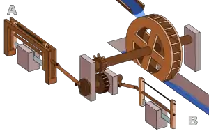
The predecessor to the connecting rod is a mechanic linkage used by water mills to convert rotating motion of the water wheel into reciprocating motion.[1]
The most common usage of connecting rods is in internal combustion engines or on steam engines.
Origins
The earliest evidence for a connecting rod appears in the late 3rd century AD Roman Hierapolis sawmill. It also appears in two 6th century Eastern Roman saw mills excavated at Ephesus respectively Gerasa. The crank and connecting rod mechanism of these Roman watermills converted the rotary motion of the waterwheel into the linear movement of the saw blades.[2]
In Renaissance Italy, the earliest evidence of a − albeit mechanically misunderstood − compound crank and connecting-rod is found in the sketch books of Taccola.[3] A sound understanding of the motion involved displays the painter Pisanello (d. 1455) who showed a piston-pump driven by a water-wheel and operated by two simple cranks and two connecting-rods.[3]
By the 16th century, evidence of cranks and connecting rods in the technological treatises and artwork of Renaissance Europe becomes abundant; Agostino Ramelli's The Diverse and Artifactitious Machines of 1588 alone depicts eighteen examples, a number which rises in the Theatrum Machinarum Novum by Georg Andreas Böckler to 45 different machines.[4]
An early documentation of the design occurred sometime between 1174—1206 AD in the Artuqid State (modern Turkey), when inventor Al-Jazari described a machine which incorporated the connecting rod with a crankshaft to pump water as part of a water-raising machine.[5][6]
Steam engines
The 1712 Newcomen atmospheric engine (the first steam engine) used chain drive instead of a connecting rod, since the piston only produced force in one direction.[7] However, most steam engines after this are double-acting, therefore the force is produced in both directions, leading to the use of a connecting rod. The typical arrangement uses a large sliding bearing block called a crosshead with the hinge between the piston and connecting rod placed outside the cylinder, requiring a seal around the piston rod.[8]
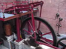
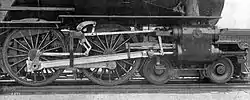
In a steam locomotive, the cranks are usually mounted directly on the driving wheels. The connecting rod is used between the crank pin on the wheel and the crosshead (where it connects to the piston rod).[9] The equivalent connecting rods on diesel locomotives are called 'side rods' or 'coupling rods'. On smaller steam locomotives, the connecting rods are usually of rectangular cross-section,[10] however marine-type rods of circular cross-section have occasionally been used.
On paddle steamers, the connecting rods are called 'pitmans' (not to be mistaken for pitman arms).
Internal combustion engines
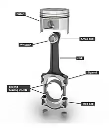
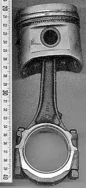
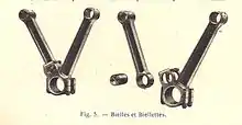
A connecting rod for an internal combustion engine consists of the 'big end', 'rod' and 'small end' (or 'little end'). The small end attaches to the gudgeon pin (also called 'piston pin' or 'wrist pin'), which can swivel in the piston. Typically, the big end connects to the crankpin using a plain bearing to reduce friction; however some smaller engines may instead use a rolling-element bearing, in order to avoid the need for a pumped lubrication system.
Typically there is a pinhole bored through the bearing on the big end of the connecting rod so that lubricating oil squirts out onto the thrust side of the cylinder wall to lubricate the travel of the pistons and piston rings.
A connecting rod can rotate at both ends, so that the angle between the connecting rod and the piston can change as the rod moves up and down and rotates around the crankshaft.
Materials
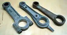
In mass-produced automotive engines, the connecting rods are most usually made of steel. In high performance applications, "billet" connecting rods can be used, which are machined out of a solid billet of metal, rather than being cast or forged.
Other materials include T6-2024 aluminium alloy or T651-7075 aluminium alloy, which are used for lightness and the ability to absorb high impact at the expense of durability. Titanium is a more expensive option which reduces the weight. Cast iron can be used for cheaper, lower performance applications such as motor scooters.
Failure during operation
During each rotation of the crankshaft, a connecting rod is often subject to large and repetitive forces: shear forces due to the angle between the piston and the crankpin, compression forces as the piston moves downwards, and tensile forces as the piston moves upwards.[11] These forces are proportional to the engine speed (RPM) squared.
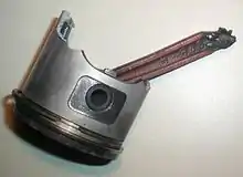
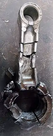
Failure of a connecting rod, often called "throwing a rod", is one of the most common causes of catastrophic engine failure in cars, frequently driving the broken rod through the side of the crankcase and thereby rendering the engine irreparable.[12] Common causes of connecting rod failure are tensile failure from high engine speeds, the impact force when the piston hits a valve (due to a valvetrain problem), rod bearing failure (usually due to a lubrication problem, or incorrect installation of the connecting rod.[13][14][15][16]
Cylinder wear
The sideways force exerted on the piston through the connecting rod by the crankshaft can cause the cylinders to wear into an oval shape. This significantly reduces engine performance, since the circular piston rings are unable to properly seal against the oval-shaped cylinder walls.
The amount of sideways force is proportional to the angle of the connecting rod, therefore longer connecting rods will reduce the amount of sideways force and engine wear. However, the maximum length of a connecting rod is constrained by the engine block size; the stroke length plus the connecting rod length must not result in the piston travelling past the top of the engine block.
Master-and-slave rods
Radial engines typically use master-and-slave connecting rods, whereby one piston (the uppermost piston in the animation), has a master rod with a direct attachment to the crankshaft. The remaining pistons pin their connecting rods' attachments to rings around the edge of the master rod.
Multi-bank engines with many cylinders, such as V12 engines, have little space available for many connecting rod journals on a limited length of crankshaft. The simplest solution, as used in most road car engines, is for each pair of cylinders to share a crank journal, but this reduces the size of the rod bearings and means that matching (ie. opposite) cylinders in the different banks are slightly offset along the crankshaft axis (which creates a rocking couple). Another solution is to use master-and-slave connecting rods, where the master rod also includes one or more ring pins which are connected to the big ends of slave rods on other cylinders. A drawback of master-slave rods is that the slave pistons' strokes will be slightly longer than that of the master piston, which increases vibration in V engines.
One of the most complicated examples of master-and-slave connecting rods is the 24-cylinder Junkers Jumo 222 experimental airplane engine developed for World War II. This engine consisted of six banks of cylinders, each with four cylinders per bank. Each "layer" of six cylinders used one master connecting rod, with the other five cylinders using slave rods.[17] Approximately 300 test engines were built, however the engine did not reach production.
Fork-and-blade rods
.jpg.webp)
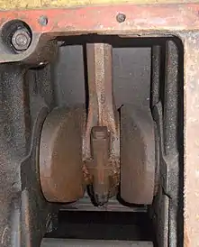
Fork-and-blade rods, also known as "split big-end rods", have been used on V-twin motorcycle engines and V12 aircraft engines.[18] For each pair of cylinders, a "fork" rod is split in two at the big end and the "blade" rod from the opposing cylinder is thinned to fit into this gap in the fork. This arrangement removes the rocking couple that is caused when cylinder pairs are offset along the crankshaft.
A common arrangement for the big-end bearing is for the fork rod to have a single wide bearing sleeve that spans the whole width of the rod, including the central gap. The blade rod then runs, not directly on the crankpin, but on the outside of this sleeve. This causes the two rods to oscillate back and forth (instead of rotating relative to each other), which reduces the forces on the bearing and the surface speed. However the bearing movement also becomes reciprocating rather than continuously rotating, which is a more difficult problem for lubrication.
Notable engines to use fork-and-blade rods include the Rolls-Royce Merlin V12 aircraft engine and various Harley Davidson V-twin motorcycle engines.
References
- Lyon, Robert L.; Editor. Steam Automobile Vol. 13, No. 3. SACA.CS1 maint: extra text: authors list (link)
- Ritti, Grewe & Kessener 2007, p. 161:
Because of the findings at Ephesus and Gerasa the invention of the crank and connecting rod system has had to be redated from the 13th to the 6th c; now the Hierapolis relief takes it back another three centuries, which confirms that water-powered stone saw mills were indeed in use when Ausonius wrote his Mosella.
- White, Jr. 1962, p. 113
- White, Jr. 1962, p. 172
- Ahmad Y Hassan. "The Crank-Connecting Rod System in a Continuously Rotating Machine".
- Sally Ganchy; Sarah Gancher (2009), Islam and Science, Medicine, and Technology, The Rosen Publishing Group, p. 41, ISBN 978-1-4358-5066-8
- "Steam Locomotive Glossary". www.railway-technical.com. Archived from the original on 2008-01-28. Retrieved 2016-02-05.
- Dempsey, G.D.; Clark, D. Kinnear (2015). The Victorian Steam Locomotive: Its Design & Development 1804-1879. Barnsley, England: Pen & Sword Transport. pp. 27–28. ISBN 978-1-47382-323-5 – via Google Books.
- Ahrons, E.L. (1921). Neale, R.E. (ed.). Steam Locomotive Construction and Maintenance. Pitman's Technical Primer Series. London: The Locomotive Publishing Co. Ltd. pp. 74–78 – via Google Books.
- White, John H., Jr. (1979). A History of the American Locomotive: Its Development, 1830-1880. New York: Dover Publications. p. 185. ISBN 9780486238180 – via Google books.
- "Causes of Failure With a Connecting Rod". www.itstillruns.com. Retrieved 21 September 2019.
- "What does it mean to "throw a rod"?". Car Talk. April 1990. Retrieved 2016-02-05.
- Policy, Privacy (15 March 2017). "Preventing Connecting Rod Failures". www.enginebuildermag.com. Retrieved 21 September 2019.
- "How to eliminate connecting rod failures". www.hotrod.com. Retrieved 21 September 2019.
- "Probable Cause of Most Rod Failures". www.arcracing.blogspot.com. 1 June 1999. Retrieved 21 September 2019.
- "Emerson Bearing Extreme Applications". www.emersonbearing.com. Retrieved 2016-02-05.
- "Drysdale Godzilla V-Twin". thekneeslider.com. Retrieved 26 September 2019.