Cylinder head
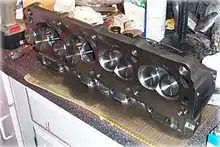
In an internal combustion engine, the cylinder head (often informally abbreviated to just head) sits above the cylinders on top of the cylinder block.[1] It closes in the top of the cylinder, forming the combustion chamber. This joint is sealed by a head gasket. In most engines, the head also provides space for the passages that feed air and fuel to the cylinder, and that allow the exhaust to escape. The head can also be a place to mount the valves, spark plugs, and fuel injectors.
Sidevalve engines
In a flathead or sidevalve engine, the mechanical parts of the valve train are all contained within the block, and a 'poultice head' may be used that is essentially a simple metal plate bolted to the top of the block.
Keeping all moving parts within the block has an advantage for physically large engines in that the camshaft drive gear is small and so suffers less from the effects of thermal expansion in the cylinder block. With a chain drive to an overhead camshaft, the extra length of chain needed for an overhead cam design could give trouble from wear and slop in the chain without frequent maintenance.
Early sidevalve engines were in use at a time of simple fuel chemistry, low octane ratings and so required low compression ratios. This made their combustion chamber design less critical and there was less need to design their ports and airflow carefully.
One difficulty experienced at this time was that the low compression ratio also implied a low expansion ratio during the power stroke.[lower-alpha 1] Exhaust gases were thus still hot, hotter than a contemporary engine, and this led to frequent trouble with burnt exhaust valves.
A major improvement to the sidevalve engine was the advent of Ricardo's turbulent head design. This reduced the space within the combustion chamber and the ports, but by careful thought about the airflow paths within them it allowed a more efficient flow in and out of the chamber. Most importantly, it used turbulence within the chamber to thoroughly mix the fuel and air mixture. This, of itself, allowed the use of higher compression ratios and more efficient engine operation.
The limit on sidevalve performance is not the gas flow through the valves, but rather the shape of the combustion chamber. With high speed engines and high compression, the limiting difficulty becomes that of achieving complete and efficient combustion, whilst also avoiding the problems of unwanted pre-detonation. The shape of a sidevalve combustion chamber, being inevitably wider than the cylinder to reach the valve ports, conflicts with achieving both an ideal shape for combustion[lower-alpha 2] and also the small volume (and low height) needed for high compression. Modern, efficient engines thus tend towards the pent roof or hemi designs, where the valves are brought close into the center of the space.
Where fuel quality is low and octane rating is poor, compression ratios will be restricted. In these cases, the sidevalve engine still has much to offer. Particularly in the case of the developed IOE engine for a market with poor fuels, engines such as Rolls-Royce B series or the Land-Rover use a complicated arrangement of inclined valves, a cylinder head line at an angle to the bore and corresponding angled pistons to provide a compact combustion chamber approaching the near-hemispherical ideal. Such engines remained in production into the 1990s, only being finally replaced when the fuels available 'in the field' became more likely to be diesel than petrol.
Detail
Internally, the cylinder head has passages called ports or tracts for the fuel/air mixture to travel to the inlet valves from the intake manifold, and for exhaust gases to travel from the exhaust valves to the exhaust manifold. In a water-cooled engine, the cylinder head also contains integral ducts and passages for the engines' coolant—usually a mixture of water and antifreeze—to facilitate the transfer of excess heat away from the head, and therefore the engine in general.
In the overhead valve (OHV) design, the cylinder head contains the poppet valves and the spark plugs, along with tracts or 'ports' for the inlet and exhaust gases. The operation of the valves is initiated by the engine's camshaft, which is sited within the cylinder block, and its moment of operation is transmitted to the valves' pushrods, and then rocker arms mounted on a rocker shaft—the rocker arms and shaft also being located within the cylinder head.
In the overhead camshaft (OHC) design, the cylinder head contains the valves, spark plugs and inlet/exhaust tracts just like the OHV engine, but the camshaft is now also contained within the cylinder head. The camshaft may be seated centrally between each offset row of inlet and exhaust valves, and still also utilizing rocker arms (but without any pushrods), or the camshaft may be seated directly above the valves eliminating the rocker arms and utilizing 'bucket' tappets.
Implementation
The number of cylinder heads in an engine is a function of the engine configuration. Almost all inline (straight) engines today use a single cylinder head that serves all the cylinders. A V (or Vee) engine has two cylinder heads, one for each cylinder bank of the 'V'. For a few compact 'narrow-angle' V engines, such as the Volkswagen VR6, the angle between the cylinder banks is so narrow that it uses a single head spanning the two banks. A flat engine (basically a V engine, where the angle between the cylinder banks is now 180°) has two heads. Most radial engines have one head for each cylinder, although this is usually of the monobloc form wherein the head is made as an integral part of the cylinder. This is also common for motorcycles, and such head/cylinder components are referred to as barrels.
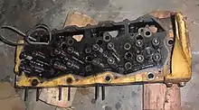
Some engines, particularly medium- and large-capacity diesel engines built for industrial, marine, power generation, and heavy traction purposes (large trucks, locomotives, heavy equipment, etc.) have individual cylinder heads for each cylinder. This reduces repair costs as a single failed head on a single cylinder can be changed instead of a larger, much more expensive unit fitting all the cylinders. Such a design also allows engine manufacturers to easily produce a 'family' of engines of different layouts and/or cylinder numbers without requiring new cylinder head designs.
The design of the cylinder head is key to the performance and efficiency of the internal combustion engine, as the shape of the combustion chamber, inlet passages and ports (and to a lesser extent the exhaust) determines a major portion of the volumetric efficiency and compression ratio of the engine.
| Common Names | Camshaft | Intake Valves | Exhaust Valves | Notes |
|---|---|---|---|---|
| Double Overhead Camshaft DOHC, Twin-Cam, Cammer | Head | Head | Head | Allows optimum positioning of the valves for a crossflow cylinder head. Double camshafts are used to allow direct actuation of well-placed valves, without rockers. Widespread in modern car design |
| Single Overhead Camshaft OHC, SOHC, Single-Cam, "Single-Jingle", Cammer | Head | Head | Head | Widely used for cars in recent decades, but increasingly superseded by DOHC. Sometimes utilizes rocker arms to actuate some valves, other times does not |
| Overhead Valve OHV, I-Head, Pushrod, Cam-In-Block | Block | Head | Head | Still used in some large-displacement V8 engines, usually of American or British origin Needs pushrods and rocker arms to actuate valves |
| Sidevalve Flathead, L-Head, T-Head | Block | Block | Block | Once universal, now obsolete Simplest possible configuration Cams operate directly on the valves |
| Inlet-Over-Exhaust IOE, F-Head, Intake-Over-Exhaust | Block | Head | Block | Always uncommon, obsolete for decades |
Gallery
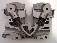 A cylinder head sliced in half showing the intake and exhaust valves, intake and exhaust ports, coolant passages, cams, tappets and valve springs.
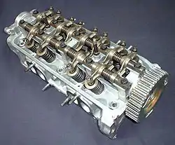
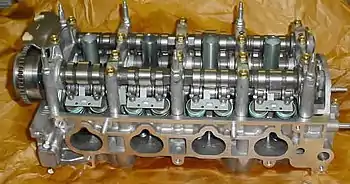 A double overhead camshaft (DOHC) cylinder head from a Honda K20Z3.
 The bottom (left) and top (right) of a Malossi cylinder head for single-cylinder, two-stroke scooters. Hole in the middle for the spark plug, four holes for the cylinder bolt posts.
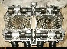 Overhead view of an air-cooled cylinder head from a Suzuki GS550 showing dual camshafts, drive sprockets and cooling fins.
Notes
- The work done on the piston during the expansion stroke is limited by how much stroke there is in which to achieve it.
- At the simplest level, a sphere approaches the ideal shape for combustion as it has the shortest paths across which to propagate the flame front. As one wall of this is the moving piston, hemispheres are more commonly chosen
References
- Wright, G. (2015). Fundamentals of Medium/Heavy Duty Diesel Engines. Jones & Bartlett Learning. p. 310. ISBN 978-1-284-06705-7. Retrieved 2020-11-07.
External links
 Media related to Cylinder heads at Wikimedia Commons
- Assembly of Ford Duratec Engine 3D simulation—video showing construction and operation of a four-cylinder internal combustion engine.
