Coupling
A coupling is a device used to connect two shafts together at their ends for the purpose of transmitting power. The primary purpose of couplings is to join two pieces of rotating equipment while permitting some degree of misalignment or end movement or both. In a more general context, a coupling can also be a mechanical device that serves to connect the ends of adjacent parts or objects.[1] Couplings do not normally allow disconnection of shafts during operation, however there are torque-limiting couplings which can slip or disconnect when some torque limit is exceeded. Selection, installation and maintenance of couplings can lead to reduced maintenance time and maintenance cost.

Uses
Shaft couplings are used in machinery for several purposes. A primary function is to transfer power from one end to another end (ex: motor transfer power to pump through coupling).
Other common uses:
- To alter the vibration characteristics of rotating units
- To connect driving and the driven part
- To introduce protection
- To reduce the transmission of shock loads from one shaft to another
- To slip when overload occurs
Types
Clamped or compression rigid couplings come in two parts and fit together around the shafts to form a sleeve. They offer more flexibility than sleeved models, and can be used on shafts that are fixed in place. They generally are large enough so that screws can pass all the way through the coupling and into the second half to ensure a secure hold. Flanged rigid couplings are designed for heavy loads or industrial equipment. They consist of short sleeves surrounded by a perpendicular flange. One coupling is placed on each shaft so the two flanges line up face to face. A series of screws or bolts can then be installed in the flanges to hold them together. Because of their size and durability, flanged units can be used to bring shafts into alignment before they are joined together.
Examples of rigid couplings
Rigid couplings are used when precise shaft alignment is required; shaft misalignment will affect the coupling's performance as well as its life.
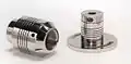
Beam coupling
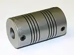
A beam coupling, also known as helical coupling, is a flexible coupling for transmitting torque between two shafts while allowing for angular misalignment, parallel offset and even axial motion, of one shaft relative to the other. This design utilizes a single piece of material and becomes flexible by removal of material along a spiral path resulting in a curved flexible beam of helical shape. Since it is made from a single piece of material, the Beam Style coupling does not exhibit the backlash found in some multi-piece couplings. Another advantage of being an all machined coupling is the possibility to incorporate features into the final product while still keep the single piece integrity.
Changes to the lead of the helical beam provide changes to misalignment capabilities as well as other performance characteristics such as torque capacity and torsional stiffness. It is even possible to have multiple starts within the same helix.
The material used to manufacture the beam coupling also affects its performance and suitability for specific applications such as food, medical and aerospace. Materials are typically aluminum alloy and stainless steel, but they can also be made in acetal, maraging steel and titanium. The most common applications are attaching rotary encoders to shafts and motion control for robotics.
 A beam coupling with optional features machined into it
_-_Angular_Misalignment.jpg.webp) Increasing number of coils allows for greater angular misalignment
Increasing number of coils allows for greater angular misalignment
Bush pin type flange coupling
This is used for slightly imperfect alignment of the two shafts.
This is modified form of the protected type flange coupling. This type of coupling has pins and it works with coupling bolts. The rubber or leather bushes are used over the pins. The coupling has two halves dissimilar in construction. The pins are rigidly fastened by nuts to one of the flange and kept loose on the other flange. This coupling is used to connect shafts which have a small parallel misalignment, angular misalignment or axial misalignment. In this coupling the rubber bushing absorbs shocks and vibration during its operations. This type of coupling is mostly used to couple electric motors and machines.
Constant velocity
There are various types of constant-velocity (CV) couplings: Rzeppa joint, Double cardan joint, and Thompson coupling.
Clamp or split-muff coupling
In this coupling, the muff or sleeve is made into two halves parts of the cast iron and they are joined together by means of mild steel studs or bolts. The advantages of this coupling is that assembling or disassembling of the coupling is possible without changing the position of the shaft. This coupling is used for heavy power transmission at moderate speed.
Diaphragm
Diaphragm couplings transmit torque from the outside diameter of a flexible plate to the inside diameter, across the spool or spacer piece, and then from inside to outside diameter. The deforming of a plate or series of plates from I.D. to O.D accomplishes the misalignment.
Disc
Disc couplings transmit torque from a driving to a driven bolt tangentially on a common bolt circle. Torque is transmitted between the bolts through a series of thin, stainless steel discs assembled in a pack. Misalignment is accomplished by deforming of the material between the bolts.
Elastic
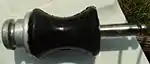
An elastic coupling transmits torque or other load by means of an elastic component. One example is the coupling used to join a windsurfing rig (sail, mast, and components) to the sailboard.[2] In windsurfing terminology it is usually called a "universal joint", but modern designs are usually based on a strong flexible material, and better technically described as an elastic coupling. They can be tendon or hourglass-shaped, and are constructed of a strong and durable elastic material. In this application, the coupling does not transmit torque, but instead transmits sail-power to the board, creating thrust (some portion of sail-power is also transmitted through the rider's body).
Flexible
Flexible couplings are usually used to transmit torque from one shaft to another when the two shafts are slightly misaligned. They can accommodate varying degrees of misalignment up to 1.5° and some parallel misalignment. They can also be used for vibration damping or noise reduction. In rotating shaft applications a flexible coupling can protect the driving and driven shaft components (such as bearings) from the harmful effects of conditions such as misaligned shafts, vibration, shock loads, and thermal expansion of the shafts or other components.
Fluid
Gear
A gear coupling is a mechanical device for transmitting torque between two shafts that are not collinear. It consists of a flexible joint fixed to each shaft. The two joints are connected by a third shaft, called the spindle.
Each joint consists of a 1:1 gear ratio internal/external gear pair. The tooth flanks and outer diameter of the external gear are crowned to allow for angular displacement between the two gears. Mechanically, the gears are equivalent to rotating splines with modified profiles. They are called gears because of the relatively large size of the teeth.
Gear couplings and universal joints are used in similar applications. Gear couplings have higher torque densities than universal joints designed to fit a given space while universal joints induce lower vibrations. The limit on torque density in universal joints is due to the limited cross sections of the cross and yoke. The gear teeth in a gear coupling have high backlash to allow for angular misalignment. The excess backlash can contribute to vibration.
Gear couplings are generally limited to angular misalignments, i.e., the angle of the spindle relative to the axes of the connected shafts, of 4–5°. Universal joints are capable of higher misalignments.
Single joint gear couplings are also used to connect two nominally coaxial shafts. In this application the device is called a gear-type flexible, or flexible coupling. The single joint allows for minor misalignments such as installation errors and changes in shaft alignment due to operating conditions. These types of gear couplings are generally limited to angular misalignments of 1/4–1/2°.
Geislinger coupling
Giubo ( sometimes misspelled as guibo) , also known as a flex disc, or Boschi joint
Grid
A grid coupling is composed of two shaft hubs, a metallic grid spring, and a split cover kit. Torque is transmitted between the two coupling shaft hubs through the metallic grid spring element.
Like metallic gear and disc couplings, grid couplings have a high torque density. A benefit of grid couplings, over either gear or disc couplings, is the ability their grid coupling spring elements have to absorb and spread peak load impact energy over time. This reduces the magnitude of peak loads and offers some vibration dampening capability. A negative of the grid coupling design is that it generally is very limited in its ability to accommodate the misalignment.[3]
Hirth
Hirth joints use tapered teeth on two shaft ends meshed together to transmit torque.
Magnetic coupling
A [magnetic] coupling uses magnetic forces to transmit the power from one shaft to another without any contact. This allows for full medium separation. Therefore can provide the ability to hermetically separate two areas whilst continuing to transmit mechanical power from one to the other making these couplings ideal for applications where prevention of cross contamination is essential.
Oldham

An Oldham coupling has three discs, one coupled to the input, one coupled to the output, and a middle disc that is joined to the first two by tongue and groove. The tongue and groove on one side is perpendicular to the tongue and groove on the other. The middle disc rotates around its center at the same speed as the input and output shafts. Its center traces a circular orbit, twice per rotation, around the midpoint between input and output shafts. Often springs are used to reduce backlash of the mechanism. An advantage to this type of coupling, as compared to two universal joints, is its compact size. The coupler is named for John Oldham who invented it in Ireland, in 1821, to solve a problem in a paddle steamer design.
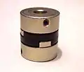 Oldham coupler, assembled
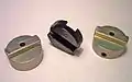 Oldham coupler, disassembled
Sleeve, box, or muff coupling
A sleeve coupling consists of a pipe whose bore is finished to the required tolerance based on the shaft size. Based on the usage of the coupling a keyway is made in the bore in order to transmit the torque by means of the key. Two threaded holes are provided in order to lock the coupling in position.
Sleeve couplings are also known as box Couplings. In this case shaft ends are coupled together and abutted against each other which are enveloped by muff or sleeve.
A gib head sunk keys hold the two shafts and sleeve together (this is the simplest type of the coupling) It is made from the cast iron and very simple to design and manufacture. It consists of a hollow pipe whose inner diameter is same as diameter of the shafts. The hollow pipe is fitted over a two or more ends of the shafts with the help of the taper sunk key. A key and sleeve are useful to transmit power from one shaft to another shaft.
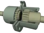
Tapered shaft lock
A tapered lock is a form of keyless shaft locking device[4] that does not require any material to be removed from the shaft. The basic idea is similar to a clamp coupling but the moment of rotation is closer to the center of the shaft.[5] An alternative coupling device to the traditional parallel key, the tapered lock removes the possibility of play due to worn keyways.[6][7][8] It is more robust than using a key because maintenance only requires one tool and the self-centering balanced rotation means it lasts longer than a keyed joint would, but the downside is that it costs more.
Twin spring coupling
A flexible coupling made from two counterwound springs with a ball bearing in the center, which allows torque transfer from input to output shaft. Requires no lubrication to consistently run as it has no internal components.[9]
Rag joint
Rag joints are commonly used on automotive steering linkages and drive trains. When used on a drive train they are sometimes known as giubos.
Universal joint
Requirements of good shaft alignment / good coupling set-up
- easy to connect or disconnect the coupling.
- does allow some misalignment between the two adjacent shaft rotation axes.
- no projecting parts
- goal should be to minimise the remaining misalignment in running operation so as to maximise power transmission and to maximise machine runtime (coupling, bearing and sealing's lifetime).
- It is recommended to use manufacturer's alignment target values to set up the machine train to a defined non-zero alignment, due to the fact that later, when the machine is at operation temperature, the alignment condition is perfect
Coupling maintenance and failure
Coupling maintenance requires a regularly scheduled inspection of each coupling. It consists of:
- Performing visual inspections,
- checking for signs of wear or fatigue
- cleaning couplings regularly
- Checking and changing lubricant regularly if the coupling is lubricated. This maintenance is required annually for most couplings and more frequently for couplings in adverse environments or in demanding operating conditions.
- Documenting the maintenance performed on each coupling, along with the date.[10]
Even with proper maintenance, however, couplings can fail. Underlying reasons for failure, other than maintenance, include:
- Improper installation
- Poor coupling selection
- Operation beyond design capabilities.[10]
The only way to improve coupling life is to understand what caused the failure and to correct it prior to installing a new coupling. Some external signs that indicate potential coupling failure include:
- Abnormal noise, such as screeching, squealing or chattering
- Excessive vibration or wobble
- Failed seals indicated by lubricant leakage or contamination.[10]
Checking the coupling balance
Couplings are normally balanced at the factory prior to being shipped, but they occasionally go out of balance in operation. Balancing can be difficult and expensive, and is normally done only when operating tolerances are such that the effort and the expense are justified. The amount of coupling unbalance that can be tolerated by any system is dictated by the characteristics of the specific connected machines and can be determined by detailed analysis or experience.[10]
References
- "Definition of COUPLING". Merriam-webster.com. Retrieved 28 November 2018.
- "Review of Windsurf Universal Joint Types – 'Your Ride, Our Gear'". Unifiber.net. Retrieved 28 November 2018.
- "Why a Grid Coupling – Features & Benefits, Design Basics, and Element Options". Couplinganswers.com. Retrieved 2014-12-22.
- "Lovejoy, Inc. : Products : Couplings & Power Transmission: Shaft Locking Devices". Lovejoy-inc.com. Archived from the original on 16 February 2015. Retrieved 7 January 2015.
- "U.S. Tsubaki POWER-LOCK Catalog" (PDF). Ustsubaki.com. Retrieved 7 January 2015.
- "Power Lock". Tsubakimoto.com. Archived from the original on 10 June 2015. Retrieved 7 January 2015.
- (PDF). 4 September 2012 https://web.archive.org/web/20120904160139/http://www.fennerdrives.com/catalogs/keyless_bushings.pdf. Archived from the original (PDF) on 2012-09-04. Retrieved 28 November 2018. Missing or empty
|title=(help) - "NEF Taper-Lock Series". Tsubakimoto.com. Retrieved 7 January 2015.
- "Twin Spring Coupling – Universal Joint and CV Joint Replacement". Twinspringcoupling.com. Retrieved 2017-07-14.
- Boyle, B. (2008). "Tracking the causes of coupling failure". Plantservices.com. Retrieved 7 January 2015.
Explore coupling maintenance and the telltale signs of failure to maximize coupling life and ensure reliable system operations
External links
| Wikimedia Commons has media related to Couplings. |
- Biography of Oldham at Cornell University
- Yutaka Nishiyama, From Oldham's Coupling to Air Conditioners
