Daniell cell
The Daniell cell is a type of electrochemical cell invented in 1836 by John Frederic Daniell, a British chemist and meteorologist, and consists of a copper pot filled with a copper (II) sulfate solution, in which is immersed an unglazed earthenware container filled with sulfuric acid and a zinc electrode. He was searching for a way to eliminate the hydrogen bubble problem found in the voltaic pile, and his solution was to use a second electrolyte to consume the hydrogen produced by the first. Zinc sulfate may be substituted for the sulfuric acid. The Daniell cell was a great improvement over the existing technology used in the early days of battery development. A later variant of the Daniell cell called the gravity cell or crowfoot cell was invented in the 1860s by a Frenchman named Callaud and became a popular choice for electrical telegraphy.

The Daniell cell is also the historical basis for the contemporary definition of the volt, which is the unit of electromotive force in the International System of Units. The definitions of electrical units that were proposed at the 1881 International Conference of Electricians were designed so that the electromotive force of the Daniell cell would be about 1.0 volts.[1][2] With contemporary definitions, the standard potential of the Daniell cell at 25 °C is actually 1.10 V.[3]
Chemistry
In the Daniell cell, copper and zinc electrodes are immersed in a solution of copper(II) sulfate and zinc sulfate, respectively. At the anode (negative electrode), zinc is oxidized per the following half reaction:
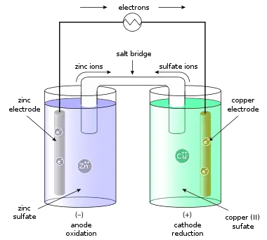
- Zn(s) → Zn2+(aq) + 2e− . . (Standard electrode reduction potential −0.7618 V )[4][5]
At the cathode (positive electrode), copper is reduced per the following reaction:
- Cu2+(aq) + 2e− → Cu(s) . . (Standard electrode reduction potential +0.340 V )
Note that positively charged copper ions move towards the positive electrode, driven by a reduction in chemical energy.
The total reaction is:
- Zn(s) + Cu2+(aq) → Zn2+(aq) + Cu(s) . . (Open-circuit voltage 1.1018 V )
These processes result in the accumulation of solid copper at the cathode and the corrosion of the zinc electrode into the solution as zinc cations. The Daniell cell produces approximately 213 kJ per mole (65 g) of zinc. This energy can mostly be attributed to the 207 kJ/mol weaker bonding (smaller magnitude of the cohesive energy) in zinc compared to copper metal, which can be explained in terms of the lack of bonding via partially filled d-orbitals in zinc.[6]
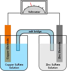
In classroom demonstrations, a form of the Daniell cell known as two half cells is often used due to its simplicity. The two half cells each support one half of the reactions described above. A wire and light bulb may connect the two electrodes. Excess electrons produced by the oxidation of zinc metal are “pushed” out of the anode, which is therefore the negative electrode, travel through the wire and are "pulled" into the copper cathode where they are consumed by the reduction of copper ions. This provides an electrical current that illuminates the bulb.
Since neither half reaction will occur independently of the other, the two half cells must be connected in a way that will allow ions to move freely between them. A porous barrier or ceramic disk may be used to separate the two solutions while allowing the flow of sulfate ions. When the half cells are placed in two entirely different and separate containers, a salt bridge is often used to connect the two cells. The salt bridge typically contains a high concentration of potassium nitrate (a salt that will not interfere chemically with the reaction in either half-cell). In the above wet-cell during discharge, nitrate anions in the salt bridge move into the zinc half-cell in order to balance the increase in Zn2+ ions. At the same time, potassium ions from the salt bridge move into the copper half-cell in order to replace the Cu2+ ions being precipitated onto the copper electrode.
If the cell is connected to a potential source (e.g. a battery charger) such that the potential difference of the source is slightly higher than the cell emf (1.1 v) then the current flow could be reversed and the reaction would become:
- Zn2+(aq) + 2e− → Zn(s)
- Cu(s) → Cu2+(aq) + 2e−
or,
- Zn2+(aq) + Cu(s) → Zn(s) + Cu2+(aq)
Hence, the Daniell cell is reversible, if the current drawn from (or fed to) it is small. The Daniell cell can be used to ‘generate’ electricity, by consuming an electrode, or to store electricity.
Development
Daniell's original construction
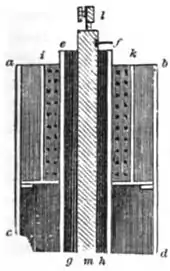
Daniell first constructed his cell in 1836.[7] His original design consisted of a 3.5 inch diameter copper cylinder. A copper disc perforated with numerous holes was placed across the cylinder recessed down from the top. A tube of ox gullet hung from a large hole in the centre of the perforated copper disc. A 0.5 inch diameter zinc rod hung inside this ox-gullet tube suspended from wooden supports. The copper vessel was filled with sulfuric acid solution saturated with copper sulfate to above the level of the perforated disc. The ox-gullet tube was filled with sulfuric acid solution. Copper sulfate crystals were piled on the perforated copper disc to keep the solution saturated. The ox-gullet acts as a porous membrane allowing passage of ions. Daniell states that a porous earthenware tube may be used instead of the ox gullet for practical ease but this arrangement will produce less power. Another suggestion made by Daniell to improve the cell was to replace the copper with platinum and copper sulfate with platinum chloride, but he remarks "such an arrangement would be perfect, but too costly for ordinary applications".[8] It is the porous pot form of the cell that came to be widely used in telegraphy.
Porous pot cell
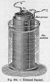
The porous pot cell consists of a central zinc anode dipped into a porous earthenware pot containing a zinc sulfate solution. The porous pot is, in turn, immersed in a solution of copper sulfate contained in a copper can, which acts as the cell's cathode. The use of a porous barrier allows ions to pass through but keeps the solutions from mixing. Without this barrier, when no current is drawn the copper ions will drift to the zinc anode and undergo reduction without producing a current, which will shorten the battery's life.[9] The replacement of sulfuric acid with zinc sulfate was the innovation of J. F. Fuller in 1853. It prolongs the life of the cell.[10]
Over time, copper buildup will block the pores in the earthenware barrier and cut short the battery's life. Nevertheless, the Daniell cell provides a longer and more reliable current than the Voltaic pile because the electrolyte deposited copper, which is a conductor, rather than hydrogen, which is an insulator, on the cathode. It is also safer and less corrosive. With an operating voltage of roughly 1.1 volts, it saw widespread use in telegraph networks until it was supplanted by the Leclanché cell in the late 1860s.[11]
Gravity cell
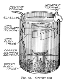
Sometime during the 1860s, a Frenchman by the name of Callaud invented a variant of the Daniell cell which dispensed with the porous barrier.[11] Instead, a layer of zinc sulfate sits on top of a layer of copper sulfate, the two liquids are kept separate by their differing densities, often with a layer of oil added on top to prevent evaporation. This reduces the internal resistance of the system and thus the battery yields a stronger current.
This variant, called a gravity cell, consists of a glass jar in which a copper cathode sat on the bottom and a zinc anode is suspended beneath the rim in the zinc sulfate layer. Copper sulfate crystals are scattered around the cathode and the jar then filled with distilled water. As the current is drawn, a layer of zinc sulfate solution forms at the top around the anode. This top layer is kept separate from the bottom copper sulfate layer by its lower density and by the polarity of the cell. A disadvantage of the gravity cell is that a current has to be continually drawn to keep the two solutions from mixing by diffusion, so it is unsuitable for intermittent use. In addition, it was vulnerable to loss of integrity if too much electric current is drawn, which also causes the layers to mix.
Sometimes called the crowfoot cell due to the distinctive shape of the electrodes, this arrangement is less costly for large multicell batteries and it quickly became the battery of choice for the American and British telegraph networks. Even after most telegraph lines started being powered by motor-generators, the gravity battery continued to be used in way stations to power the local circuit at least into the 1950s.[12] In the telegraph industry, this battery was often assembled on site by the telegraph workers themselves, and when it ran down it could be renewed by replacing the consumed components.[13] The zinc sulfate layer is clear in contrast to the deep blue copper sulfate layer, which allows a technician to determine the battery life with a glance. On the other hand, this setup means the battery could only be used in a stationary appliance, otherwise the solutions would mix or spill.
Use in electrometallurgy
Bird's cell
A variant of the Daniell cell was invented in 1837 by the Guy's hospital physician Golding Bird who used a plaster of Paris barrier to keep the solutions separate. Bird's experiments with this cell were of some importance to the new discipline of electrometallurgy, but Bird himself did not pursue this field; his interest was in electrotherapy. A surprising result from Bird's experiments was the deposition of copper on the porous plaster and in veins running through it without any contact with the metal electrodes. So surprising, in fact, that it was at first disbelieved by electrochemical investigators, including Michael Faraday. Bird himself had to carefully examine his apparatus for inadvertent contact, perhaps through the growth of copper "whiskers", before he was convinced of the result. Deposition of copper, and other metals, had been previously noted, but always previously it had been metal on metal electrode.[14][15]
Electrotyping
John Dancer, a Liverpool instrument maker, in 1838 was the first to take commercial advantage of the unique features of the Daniell cell for copper plating. In a process now known as electrotyping he found he could make objects to any desired shape by using the porous barrier as a mould. Many others, however, had made the same discovery and in a patent dispute with Thomas Spencer it was pointed out that Bird had priority for the principle. Credit for invention of electrotyping is usually given to the Russian Moritz von Jacobi.[14]
See also
| Wikimedia Commons has media related to Daniell cell. |
References
- Borvon, Gérard (September 10, 2012). "History of the electrical units". Association S-EAU-S.
- Hamer, Walter J. (January 15, 1965). Standard Cells: Their Construction, Maintenance, and Characteristics (PDF). National Bureau of Standards Monograph #84. US National Bureau of Standards.
- Spencer, James N.; Bodner, George M.; Rickard, Lyman H. (2010). Chemistry: Structure and Dynamics (Fifth Edition). John Wiley & Sons. p. 564. ISBN 9780470587119.
- Michael Clugston, Rosalind Flemming, Advanced Chemistry, p. 224, Oxford University Press, 2000 ISBN 0199146330.
- National Bureau of Standards, Zinc and its Alloys, p. 40, U.S. Government Printing Office, 1931 OCLC 954241601.
- Schmidt-Rohr, K. (2018). "How Batteries Store and Release Energy: Explaining Basic Electrochemistry" J. Chem. Educ. 95: 1801-1810. https://doi.org/10.1021/acs.jchemed.8b00479
- Elizabeth H. Oakes, A to Z of STS Scientists, p. 72, Infobase Publishing, 2009 ISBN 1438109253.
- John Frederic Daniell, An Introduction to the Study of Chemical Philosophy, pp. 504–505, John W. Parker, 1843 OCLC 315534231 (pp. 438–439 in 1839 edition OCLC 7841489 in which the comments about platinum do not appear).
- Giorgio Carboni, Experiments in Electrochemistry; Last accessed on Jul 30, 2010.
- Thomas Kingston Derry, Trevor Illtyd Williams, A Short History of Technology from the Earliest Times to A.D. 1900, p. 611, Courier Corporation, 1960 ISBN 9780486274720.
- James B. Calvert. "The Electromagnetic Telegraph". Archived from the original on 2007-08-04. Retrieved 2010-07-30.
- Tools of Telegraphy Archived 2011-07-23 at the Wayback Machine, Telegraph Lore; Last accessed Jul 30, 2010
- Gregory S. Raven, Recollections of a Narrow Gauge Lightning Slinger Archived 2011-07-23 at the Wayback Machine; Last accessed on Jul 30, 2010.
- Watt, Alexander; Philip, Arnold (2005). Electroplating and Electrorefining of Metals. Watchmaker Publishing. pp. 90–92. ISBN 1929148453. Reprint of an 1889 volume.
- Golding Bird, Report of the Seventh Meeting of the British Society for the Advancement of Science, vol.6 (1837), p.45, London: J. Murray, 1838.
Further reading
- Saslow, Wayne M. (1999), "Voltaic cells for physicists: Two surface pumps and an internal resistance", American Journal of Physics, 67 (7): 574–583, Bibcode:1999AmJPh..67..574S, doi:10.1119/1.19327
- Lester, James C.; Vicari, Rosa Maria; Paraguaçu, Fábio (2004), Lester, James C.; Vicari, Rosa Maria; Paraguaçu, Fábio (eds.), A Qualitative Model of Daniell Cell for Chemical Education, Lecture Notes in Computer Science, 3220, doi:10.1007/b100137, ISBN 978-3-540-22948-3
