Optical comparator
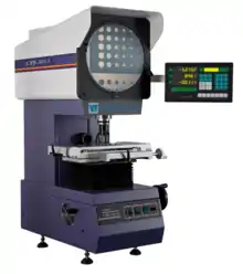
An optical comparator (often called just a comparator in context) or profile projector is a device that applies the principles of optics to the inspection of manufactured parts. In a comparator, the magnified silhouette of a part is projected upon the screen, and the dimensions and geometry of the part are measured against prescribed limits. It is a useful item in a small parts machine shop or production line for the quality control inspection team.


The measuring happens in any of several ways. The simplest way is that graduations on the screen, being superimposed over the silhouette, allow the viewer to measure, as if a clear ruler were laid over the image. Another way is that various points on the silhouette are lined up with the reticle at the centerpoint of the screen, one after another, by moving the stage on which the part sits, and a digital read out reports how far the stage moved to reach those points. Finally, the most technologically advanced methods involve software that analyzes the image and reports measurements. The first two methods are the most common; the third is newer and not as widespread, but its adoption is ongoing in the digital era.
History
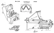
The first commercial comparator was developed by James Hartness and Russell W. Porter.[2] Hartness' long-continuing work as the Chairman of the U.S.'s National Screw-Thread Commission led him to apply his familiarity with optics (from his avocations of astronomy and telescope-building) to the problem of screw thread inspection. The Hartness Screw-Thread Comparator was for many years a profitable product for the Jones and Lamson Machine Company, of which he was president.
In subsequent decades optical comparators have been made by many companies and have been applied to the inspection of many kinds of parts. Today they may be found in many machine shops.[3]
The idea of mixing optics and measurement, and the use of the term comparator for metrological equipment, had existed in other forms prior to Hartness's work; but they had remained in realms of pure science (such as telescopy and microscopy) and highly specialized applied science (such as comparing master measuring standards). Hartness's comparator, intended for the routine inspection of machined parts, was a natural next step in the era during which applied science became widely integrated into industrial production.
Usage
The profile projector is widely used for complex-shape stampings, gears, cams, threads and comparing the measured contour model. The profile projector is hence widely used in precision machinery manufacturing, including aviation, aerospace industry, watches and clocks, electronics, instrumentation industry, research institutes and detection metering stations at all levels, etc.
Work principle

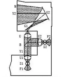
The projector magnifies the profile of the specimen, and displays this on the built-in projection screen.
[4] On this screen there is typically a grid that can be rotated 360 degrees so the X-Y axis of the screen can be aligned with a straight edge of the machined part to examine or measure. This projection screen displays the profile of the specimen and is magnified for better ease of calculating linear measurements.
An edge of the specimen to examine may be lined up with the grid on the screen. From there, simple measurements may be taken for distances to other points. This is being done on a magnified profile of the specimen. It can be simpler as well as reduce errors by measuring on the magnified projection screen of a profile projector.
The typical method for lighting is by diascopic illumination, which is lighting from behind. This type of lighting is also called transmitted illumination when the specimen is translucent and light can pass through it. If the specimen is opaque, then the light will not go through it, but will form a profile of the specimen.
Measuring of the sample can be done on the projection screen. A profile projector may also have episcopic illumination (which is light shining from above). This is useful in displaying bores or internal areas that may need to be measured.
Features
Projection methods
- Vertical projectors: The main axis is parallel to the plane of the screen. They're most common, and suitable for flat parts or smaller work-pieces.
- Horizontal Projector: The main axis is perpendicular to the plane of the projection screen. Screens are thus made mainly in medium and large versions generally suited for examining shaft parts or heavy work-pieces with large profiles, although having a horizontal table below without a hole for light transmission can be convenient for small machines with a silhouette lighting arrangement.
Positive or inverted images
For the simplest type of profile projector, the part's inverted image, also known as its mirror image, will be displayed on the screen.
In order to facilitate the measurement, sometimes a plus-image system is deliberately added, changing the inverted image into a positive one, which increases the cost due to scale/material used, while somewhat reducing its measurement accuracy.
Screen size
As for selection of screen size, one should carefully consider whether the entire part must be imaged on the screen. If the inspection can readily be done at a modest scale, there is no need for a larger screen. Projector manufacturers offer multiple screen sizes to meet various needs.
Magnification
The projection lens magnification is fixed. Different views of measured pieces often require different magnifications. However, the usual projector factory configuration is with a single lens, so according to needs, additional lenses may be purchased and used.
Work table and accessories
The work table is used to place and hold the measured piece. Its own volume, X, Y travel and carrying capacity are critical. Meanwhile, for the convenience of holding the workpiece, a precision rotary table, a V-block part holder and other accessories are generally added.
Also, the projector must have a flexible and stable focusing mechanism and large working distance (the top surface of the workpiece relative to the lens pitch). The user selects appropriate data processing modes: without exception, all modern optical measuring projectors on market have been digitized. We will therefore also consider relevant data-processing capabilities.
See also
References
- Hartness, James; Porter, Russell (1929). "United States Patent 1703933: Optical comparator". U.S. Patent Office. Cite journal requires
|journal=(help) - Roe 1937, pp. 43–45.
- Smith, Kennedy (2002). "Shedding light on optical comparators—How much better can this type of system get?". Quality Digest: QCI International. Retrieved 2008-05-12.
- Leung, Sonny. "What Is Profile Projector". Vision Measuring Machine and Profile Projector. Retrieved 8 December 2016.
Bibliography
- Roe, Joseph Wickham (1937), James Hartness: A Representative of the Machine Age at Its Best, New York, New York, USA: American Society of Mechanical Engineers, LCCN 37016470, OCLC 3456642. link from HathiTrust.
