POWER3
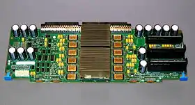
The POWER3 is a microprocessor, designed and exclusively manufactured by IBM, that implemented the 64-bit version of the PowerPC instruction set architecture (ISA), including all of the optional instructions of the ISA (at the time) such as instructions present in the POWER2 version of the POWER ISA but not in the PowerPC ISA. It was introduced on 5 October 1998, debuting in the RS/6000 43P Model 260, a high-end graphics workstation.[1] The POWER3 was originally supposed to be called the PowerPC 630 but was renamed, probably to differentiate the server-oriented POWER processors it replaced from the more consumer-oriented 32-bit PowerPCs. The POWER3 was the successor of the P2SC derivative of the POWER2 and completed IBM's long-delayed transition from POWER to PowerPC, which was originally scheduled to conclude in 1995. The POWER3 was used in IBM RS/6000 servers and workstations at 200 MHz. It competed with the Digital Equipment Corporation (DEC) Alpha 21264 and the Hewlett-Packard (HP) PA-8500.
| General information | |
|---|---|
| Launched | 1998 |
| Designed by | IBM |
| Architecture and classification | |
| Instruction set | PowerPC |
| History | |
| Predecessor | POWER2 |
| Successor | POWER4 |
| POWER, PowerPC, and Power ISA architectures |
|---|
| NXP (formerly Freescale and Motorola) |
| IBM |
|
| IBM/Nintendo |
| Other |
| Related links |
|
| Cancelled in gray, historic in italic |

Description

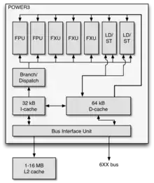
The POWER3 was based on the PowerPC 620, an earlier 64-bit PowerPC implementation that was late, under-performing and commercially unsuccessful. Like the PowerPC 620, the POWER3 has three fixed-point units, but the single floating-point unit (FPU) was replaced with two floating-point fused multiply–add units, and an extra load-store unit was added (for a total of two) to improve floating-point performance. The POWER3 is a superscalar design that executed instructions out of order. It has a seven-stage integer pipeline, a minimal eight-stage load/store pipeline and a ten-stage floating-point pipeline.
The front end consists of two stages: fetch and decode. During the first stage, eight instructions were fetched from a 32 KB instruction cache and placed in a 12-entry instruction buffer. During the second stage, four instructions were taken from the instruction buffer, decoded, and issued to instruction queues. Restrictions on instruction issue are few: of the two integer instruction queues, only one can accept one instruction, the other can accept up to four, as does the floating-point instruction queue. If the queues do not have enough unused entries, instructions cannot be issued. The front end has a short pipeline, resulting in a small three-cycle branch misprediction penalty.
In stage three, instructions in the instruction queues that are ready for execution have their operands read from the register files. The general-purpose register file contains 48 registers, of which 32 are general-purpose registers and 16 are rename registers for register renaming. To reduce the number of ports required to provide data and receive results, the general purpose register file is duplicated so that there are two copies, the first supporting three integer execution units and the second supporting the two load/store units. This scheme was similar to a contemporary microprocessor, the DEC Alpha 21264, but was simpler as it did not require an extra clock cycle to synchronize the two copies due to the POWER3's higher cycle times. The floating-point register file contains 56 registers, of which 32 are floating-point registers and 24 rename registers. Compared to the PowerPC 620, there were more rename registers, which allowed more instructions to be executed out of order, improving performance.
Execution begins in stage four. The instruction queues dispatch up to eight instructions to the execution units. Integer instructions are executed in three integer execution units (termed "fixed-point units" by IBM). Two of the units are identical and execute all integer instructions except for multiply and divide. All instructions executed by them have a one-cycle latency. The third unit executes multiply and divide instructions. These instructions are not pipelined and have multi-cycle latencies. 64-bit multiply has a nine-cycle latency and 64-bit divide has a 37-cycle latency.
Floating-point instructions are executed in two floating-point units (FPUs). The FPUs are capable of fused multiply–add, where multiplication and addition is performed simultaneously. Such instructions, along with individual add and multiply, have a four-cycle latency. Divide and square-root instructions are executed in the same FPUs, but are assisted by specialized hardware. Single-precision (32-bit) divide and square-root instructions have a 14-cycle latency, whereas double-precision (64-bit) divide and square-root instructions have an 18-cycle and a 22-cycle latency, respectively.
After execution is completed, the instructions are held in buffers before being committed and made visible to software. Execution finishes in stage five for integer instructions and stage eight for floating-point. Committing occurs during stage six for integers, stage nine for floating-point. Writeback occurs in the stage after commit. The POWER3 can retire up to four instructions per cycle.
The PowerPC 620 data cache was optimized for technical and scientific applications. Its capacity was doubled to 64 KB, to improve the cache-hit rate; the cache was dual-ported, implemented by interleaving eight banks, to enable two loads or two stores to be performed in one cycle in certain cases; and the line-size was increased to 128-bytes. The L2 cache bus was doubled in width to 256 bits to compensate for the larger cache line size and to retain a four-cycle latency for cache refills.
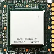
The POWER3 contained 15 million transistors on a 270 mm2 die. It was fabricated in IBM's CMOS-6S2 process, a complementary metal–oxide–semiconductor process that is a hybrid of 0.25 μm feature sizes and 0.35 μm metal layers. The process features five layers of aluminium. It was packaged in the same 1,088-column ceramic column grid array as the P2SC, but with a different pin out.
POWER3-II

The POWER3-II was an improved POWER3 that increased the clock frequency to 450 MHz. It contains 23 million transistors and measured 170 mm2. It was fabricated in the IBM CMOS7S process, a 0.22 μm CMOS process with six levels of copper interconnect. It was succeeded by the POWER4 in 2001.
Notes
- New IBM POWER3 chip.
References
- Papermaster, M.; Dinkjian, R.; Mayfield, M.; et al. (1998). "POWER3: Next Generation 64-bit PowerPC Processor Design". IBM Corp. Cite journal requires
|journal=(help) - Anderson, S.; Bell, R.; Hague, J.; et al. (1998). "RS/6000 Scientific and Technical Computing: POWER3 Introduction and Tuning Guide" (PDF). IBM Corp. Archived from the original (PDF) on 2006-07-21. Cite journal requires
|journal=(help) - gives more information about POWER1, POWER2, and POWER3 - O'Connell, F. P.; White, S. W. (6 November 2000). "POWER3: The next generation of PowerPC processors". IBM Journal of Research and Development, Volume 44, Number 6.
- Song, Peter (17 November 1997). "IBM's Power3 to Replace P2SC". Microprocessor Report.
- International Business Machines Corporation (5 October 1998). New IBM POWER3 chip. Press release.