Antenna aperture
In electromagnetics and antenna theory, antenna aperture, effective area, or receiving cross section, is a measure of how effective an antenna is at receiving the power of electromagnetic radiation (such as radio waves).[1] The aperture is defined as the area, oriented perpendicular to the direction of an incoming electromagnetic wave, which would intercept the same amount of power from that wave as is produced by the antenna receiving it. At any point , a beam of electromagnetic radiation has an irradiance or power flux density which is the amount of power passing through a unit area of one square meter. If an antenna delivers watts to the load connected to its output terminals (e.g. the receiver) when irradiated by a uniform field of power density watts per square meter, the antenna's aperture in square meters is given by:[2]


- .

So the power received by an antenna (in watts) is equal to the power density of the electromagnetic energy (in watts per square meter), multiplied by its aperture (in square meters). The larger an antenna's aperture, the more power it can collect from a given electromagnetic field. To actually obtain the predicted power available , the polarization of the incoming waves must match the polarization of the antenna, and the load (receiver) must be impedance matched to the antenna's feedpoint impedance.
Although this concept is based on an antenna receiving an electromagnetic wave, knowing directly supplies the (power) gain of that antenna. Due to reciprocity, an antenna's gain in receiving and transmitting are identical. Therefore, can be used to compute the performance of a transmitting antenna also. is a function of the direction of the electromagnetic wave relative to the orientation of the antenna, since the gain of an antenna varies according to its radiation pattern. When no direction is specified, is understood to refer to its maximum value, with the antenna oriented so its main lobe, the axis of maximum sensitivity, is directed toward the source .
Aperture efficiency
In general, the aperture of an antenna is not directly related to its physical size.[3] However some types of antennas, for example parabolic dishes and horn antennas, have a physical aperture (opening) which collects the radio waves. In these aperture antennas, the effective aperture is always less than the area of the antenna's physical aperture , otherwise the antenna could produce more power from its terminals than the radio power entering its aperture, violating conservation of energy. An antenna's aperture efficiency, is defined as the ratio of these two areas:


The aperture efficiency is a dimensionless parameter between 0 and 1.0 that measures how close the antenna comes to using all the radio wave power entering its physical aperture. If the antenna were perfectly efficient, all the radio power falling within its physical aperture would be converted to electrical power delivered to the load attached to its output terminals, so these two areas would be equal and the aperture efficiency would be 1.0. But all antennas have losses, such as power dissipated as heat in the resistance of its elements, nonuniform illumination by its feed, and radio waves scattered by structural supports and diffraction at the aperture edge, which reduce the power output. Aperture efficiencies of typical antennas vary from 0.35 to 0.70 but can range up to 0.90.

Aperture and gain
The directivity of an antenna, its ability to direct radio waves in one direction or receive from a single direction, is measured by a parameter called its isotropic gain , which is the ratio of the power received by the antenna to the power that would be received by a hypothetical isotropic antenna, which receives power equally well from all directions. It can be seen that gain is also equal to the ratio of the apertures of these antennas


As shown in the section at bottom, the aperture of a lossless isotropic antenna, which by definition has unity gain, is

where is the wavelength of the radio waves. So


and for an antenna with a physical aperture of area

So antennas with large effective apertures are high gain antennas, which have small angular beam widths. As receiving antennas, they are most sensitive to radio waves coming from one direction, and are much less sensitive to waves coming from other directions. As transmitting antennas, most of their power is radiated in a narrow beam in one direction, and little in other directions. Although these terms can be used as a function of direction, when no direction is specified, the gain and aperture are understood to refer to the antenna's axis of maximum gain, or boresight.
Friis transmission formula
The fraction of the power delivered to a transmitting antenna that is received by a receiving antenna is proportional to the product of the apertures of both the antennas and inversely proportional to the distance between the antennas and wavelength. This is given by a form of the Friis transmission formula:.[1]

where:
- is the power fed into the transmitting antenna input terminals;[1]
- is the power available at receiving antenna output terminals;[1]
- is the effective area of the receiving antenna;[1]
- is the effective area of the transmitting antenna;[1]
- is the distance between antennas.[1] The formula is only valid for large enough to ensure a plane wave front at the receive antenna, sufficiently approximated by where is the largest linear dimension of either of the antennas.[1]
- is the wavelength of the radio frequency;[1]


The variables , , , and must be expressed in the same units of length, such as meters, and variables and must be in the same units of power, such as watts.
Thin element antennas
In the case of thin element antennas such as monopoles and dipoles, there is no simple relationship between physical area and effective area. However, the effective areas can be calculated from their power gain figures:[4]
| Wire antenna | Power gain | Effective area |
|---|---|---|
| Short dipole (Hertzian dipole) | 1.5 | 0.1194 2 |
| Half-wave dipole | 1.64 | 0.1305 2 |
| Quarter-wave monopole | 3.28 | 0.2610 2[5] |
This assumes that the monopole antenna is mounted above an infinite ground plane and that the antennas are lossless. When resistive losses are taken into account, particularly with small antennas, the antenna gain might be substantially less than the directivity, and the effective area is less by the same factor.[6]
Effective length
For antennas which are not defined by a physical area, such as monopoles and dipoles consisting of thin rod conductors, the aperture bears no obvious relation to the size or area of the antenna. An alternate measure of antenna gain that has a greater relationship to the physical structure of such antennas is effective length leff measured in metres, which is defined for a receiving antenna as:[7]

where
- V0 is the open circuit voltage appearing across the antenna's terminals
- Es is the electric field strength of the radio signal, in volts per metre, at the antenna.
The longer the effective length the more voltage and therefore the more power the antenna will receive. An antenna's gain or Aeff increases according to the square of leff, and that this proportionality also involves the antenna's radiation resistance. Therefore, this measure is of more theoretical than practical value and is not, by itself, a useful figure of merit relating to an antenna's directivity.
Derivation of aperture of an isotropic antenna
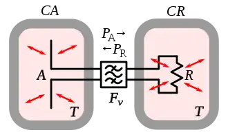


The aperture of an isotropic antenna, the basis of the definition of gain above, can be derived by a thermodynamic argument.[8][9][10] Suppose an ideal (lossless) isotropic antenna A located within a thermal cavity CA, is connected via a lossless transmission line through a band-pass filter Fν to a matched resistor R in another thermal cavity CR (the characteristic impedance of the antenna, line and filter are all matched). Both cavities are at the same temperature . The filter Fν only allows through a narrow band of frequencies from to . Both cavities are filled with blackbody radiation in equilibrium with the antenna and resistor. Some of this radiation is received by the antenna. The amount of this power within the band of frequencies passes through the transmission line and filter Fν and is dissipated as heat in the resistor. The rest is reflected by the filter back to the antenna and is reradiated into the cavity. The resistor also produces Johnson–Nyquist noise current due to the random motion of its molecules at the temperature . The amount of this power within the frequency band to passes through the filter and is radiated by the antenna. Since the system is at a common temperature it is in thermodynamic equilibrium; there can be no net transfer of power between the cavities, otherwise one cavity would heat up and the other would cool down in violation of the second law of thermodynamics. Therefore, the power flows in both directions must be equal


The radio noise in the cavity is unpolarized, containing an equal mixture of polarization states. However any antenna with a single output is polarized, and can only receive one of two orthogonal polarization states. For example, a linearly polarized antenna cannot receive components of radio waves with electric field perpendicular to the antenna's linear elements; similarly a right circularly polarized antenna cannot receive left circularly polarized waves. Therefore, the antenna only receives the component of power density S in the cavity matched to its polarization, which is half of the total power density

Suppose is the spectral radiance per hertz in the cavity; the power of black-body radiation per unit area (meter2) per unit solid angle (steradian) per unit frequency (hertz) at frequency and temperature in the cavity. If is the antenna's aperture, the amount of power in the frequency range the antenna receives from an increment of solid angle in the direction is


To find the total power in the frequency range the antenna receives, this is integrated over all directions (a solid angle of )


Since the antenna is isotropic, it has the same aperture in any direction. So the aperture can be moved outside the integral. Similarly the radiance in the cavity is the same in any direction


Radio waves are low enough in frequency so the Rayleigh–Jeans formula gives a very close approximation of the blackbody spectral radiance[11]

Therefore,

The Johnson–Nyquist noise power produced by a resistor at temperature over a frequency range is

Since the cavities are in thermodynamic equilibrium , so


References
- Friis, H.T. (May 1946). "A Note on a Simple Transmission Formula". IRE Proc. 34 (5): 254–256. doi:10.1109/JRPROC.1946.234568. S2CID 51630329.
- Bakshi, K.A.; A.V.Bakshi, U.A.Bakshi (2009). Antennas And Wave Propagation. Technical Publications. p. 1.17. ISBN 978-81-8431-278-2.
- Narayan, C.P. (2007). Antennas And Propagation. Technical Publications. p. 51. ISBN 978-81-8431-176-1.
- Orfanidis, Sophocles J. (2010) Electromagnetic Waves and Antennas chapter 15 page 609, retrieved 2011-04-05 from http://www.ece.rutgers.edu/~orfanidi/ewa/
- Orfanidis, Sophocles J. (2010) Electromagnetic Waves and Antennas chapter 16 page 747, retrieved 2011-04-05 from http://www.ece.rutgers.edu/~orfanidi/ewa/
- Weeks, W.L. (1968) Antenna Engineering, McGraw Hill Book Company, chapters 8, pp. 297-299 and 9, pp. 343-346.
- Rudge, Alan W. (1982). The Handbook of Antenna Design, Vol. 1. USA: IET. p. 24. ISBN 0-906048-82-6.
- Pawsey, J. L.; Bracewell, R. N. (1955). Radio Astronomy. London: Oxford University Press. pp. 23–24.
- Rohlfs, Kristen; Wilson, T. L. (2013). Tools of Radio Astronomy, 4th Edition. Springer Science and Business Media. pp. 134–135. ISBN 978-3662053942.
- Condon, J. J.; Ransom, S. M. (2016). "Antenna Fundamentals". Essential Radio Astronomy course. US National Radio Astronomy Observatory (NRAO) website. Retrieved 22 August 2018.
- The Rayleigh-Jeans formula is a good approximation as long as the energy in a radio photon is small compared with the thermal energy per degree of freedom: . This is true throughout the radio spectrum at all ordinary temperatures.

