Directivity
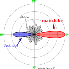
In electromagnetics, directivity is a parameter of an antenna or optical system which measures the degree to which the radiation emitted is concentrated in a single direction. It measures the power density the antenna radiates in the direction of its strongest emission, versus the power density radiated by an ideal isotropic radiator (which emits uniformly in all directions) radiating the same total power.
| Part of a series on |
| Antennas |
|---|
 |
An antenna's directivity is a component of its gain; the other component is its (electrical) efficiency. Directivity is an important measure because many antennas and optical systems are designed to radiate electromagnetic waves in a single direction or over a narrow-angle. Directivity is also defined for an antenna receiving electromagnetic waves, and its directivity when receiving is equal to its directivity when transmitting.
The directivity of an actual antenna can vary from 1.76 dBi for a short dipole to as much as 50 dBi for a large dish antenna.[1]
Definition
The directivity, , of an antenna is the maximal value of its directive gain. Directive gain is represented as and compares the radiant intensity (power per unit solid angle) that an antenna creates in a particular direction against the average value over all directions:


Here and are the zenith angle and azimuth angle respectively in the standard spherical coordinate angles; is the radiation intensity, which is the power per unit solid angle; and is the total radiated power. The quantities and satisfy the relation


that is, the total radiated power is the power per unit solid angle integrated over a spherical surface. Since there are 4π steradians on the surface of a sphere, the quantity represents the average power per unit solid angle.

In other words, directive gain is the radiation intensity of an antenna at a particular coordinate combination divided by what the radiation intensity would have been had the antenna been an isotropic antenna radiating the same amount of total power into space.

Directivity, then, is the maximal directive gain value found among all possible solid angles:

The word directivity is also sometimes used as a synonym for directive gain. This usage is readily understood, as the direction will be specified, or directional dependence implied. Later editions of the IEEE Dictionary[2] specifically endorse this usage; nevertheless it has yet to be universally adopted.
In antenna arrays
In an antenna array (a set of multiple identical antennas which work together as a single antenna), the directivity of the entire array is the multiplicative sum of the individual antenna's directivity function with a mathematical expression known as the array factor , which typically depends on the location, the excitation and the phase of each antenna element.[3][4] The overall directivity[5] function is given by

- ,

where is the directivity of a single element. This single element term is sometimes referred to as the element pattern.[6]
Relation to beam width
The beam solid angle, represented as , is defined as the solid angle which all power would flow through if the antenna radiation intensity were constant at its maximal value. If the beam solid angle is known, then maximum directivity can be calculated as


which simply calculates the ratio of the beam solid angle to the solid angle of a sphere.
The beam solid angle can be approximated for antennas with one narrow major lobe and very negligible minor lobes by simply multiplying the half-power beamwidths (in radians) in two perpendicular planes. The half-power beamwidth is simply the angle in which the radiation intensity is at least half of the peak radiation intensity.
The same calculations can be performed in degrees rather than in radians:

where is the half-power beamwidth in one plane (in degrees) and is the half-power beamwidth in a plane at a right angle to the other (in degrees).


In planar arrays, a better approximation is

For an antenna with a conical (or approximately conical) beam with a half-power beamwidth of degrees, then elementary integral calculus yields an expression for the directivity as
- .

Expression in decibels
The directivity is rarely expressed as the unitless number but rather as a decibel comparison to a reference antenna:

The reference antenna is usually the theoretical perfect isotropic radiator, which radiates uniformly in all directions and hence has a directivity of 1. The calculation is therefore simplified to

Another common reference antenna is the theoretical perfect half-wave dipole, which radiates perpendicular to itself with a directivity of 1.64:

Accounting for polarization
When polarization is taken under consideration, three additional measures can be calculated:
Partial directive gain
Partial directive gain is the power density in a particular direction and for a particular component of the polarization, divided by the average power density for all directions and all polarizations. For any pair of orthogonal polarizations (such as left-hand-circular and right-hand-circular), the individual power densities simply add to give the total power density. Thus, if expressed as dimensionless ratios rather than in dB, the total directive gain is equal to the sum of the two partial directive gains.[2]
Partial directivity
Partial directivity is calculated in the same manner as the partial directive gain, but without consideration of antenna efficiency (i.e. assuming a lossless antenna). It is similarly additive for orthogonal polarizations.
Partial gain
Partial gain is calculated in the same manner as gain, but considering only a certain polarization. It is similarly additive for orthogonal polarizations.
In other areas
The term directivity is also used with other systems.
With directional couplers, directivity is a measure of the difference in dB of the power output at a coupled port, when power is transmitted in the desired direction, to the power output at the same coupled port when the same amount of power is transmitted in the opposite direction.[7]
In acoustics, it is used as a measure of the radiation pattern from a source indicating how much of the total energy from the source is radiating in a particular direction. In electro-acoustics, these patterns commonly include omnidirectional, cardioid and hyper-cardioid microphone polar patterns. A loudspeaker with a high degree of directivity (narrow dispersion pattern) can be said to have a high Q.[8]
References
- Antenna Tutorial
- Institute of Electrical and Electronics Engineers, “The IEEE standard dictionary of electrical and electronics terms”; 6th ed. New York, N.Y., Institute of Electrical and Electronics Engineers, c1997. IEEE Std 100-1996. ISBN 1-55937-833-6 [ed. Standards Coordinating Committee 10, Terms and Definitions; Jane Radatz, (chair)]
- "Array factors" (PDF). Retrieved 19 June 2015.
- "Antennas and Propagation" (PDF). Jacobs university. Retrieved 19 June 2015.
- "Antenna Arrays" (PDF).
- Electronically Scanned Arrays by Arik D. Brown
- App note, Mini-Circuits directional couplers
- AES Professional Audio Reference definition of Q
- Coleman, Christopher (2004). "Basic Concepts". An Introduction to Radio Frequency Engineering. Cambridge University Press. ISBN 0-521-83481-3.
