Antenna feed
In telecommunications and electronics, an antenna feed refers to several slightly different parts of an antenna system:
- The antenna feed is the wire or cabling (transmission line) that connects between the antenna and the radio, specifically called the feed line.
- The antenna feed is the location on the antenna where the feedline from the receiver or transmitter connects or attaches.
- The antenna feed is the matching system at the attachment point that converts the feedline impedance to the antenna's intrinsic impedance, and makes any balanced-to-unbalanced conversion (if necessary).
| Part of a series on |
| Antennas |
|---|
 |
In a transmitting antenna system the term can refer to any one or all of the components involved conveying the RF electrical current into the radiating part of the antenna, where the current is converted to radiation; in a receiving antenna, the term refers to the parts of the system that convert the electric currents already collected from incoming radio waves into a specific voltage to current ratio (impedance) needed at the receiver.
Because of the several meanings, antenna feed system is used to specifically refer to all of the parts of the antenna feed between the radio and the radiator.
Simple and compound antennas
Simple antennas, such as monopole or whip antennas, dipole antennas, and large loop antennas are often directly connected to a feedline cable that matches the impedance of the antenna and the radio.
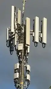
Compound antennas are made of multiple simple antennas, similar to the way that compound lenses are made of several simple lenses. Examples of compound antennas are array antennas, Yagi-Uda antennas, log periodic antennas, quad antennas, and small loop antennas (when fed by an even-smaller loop).
Often, one of the simple sub-antennas that is part of a compound antenna is a feeder antenna, also called the driven element: The driven element converts the RF electrical currents to free space radio waves, or vice versa. It radiates the signal into the space nearby the other elements of the compound antenna, which in turn absorb and re-radiate the signal (such as a parabolic dish). Those elements are called "passive" or "parasitic" elements and they re-radiate the radio waves they absorb in the form of a beam in the desired direction.[lower-alpha 1] The passive elements function as reflecting and directing structures in the same way that mirrors and focusing lenses function in compound lenses.
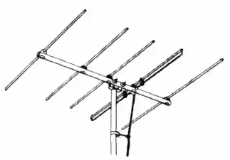
For example, in a rooftop Yagi-Uda television antenna, the feed consists of a dipole driven element, which converts the radio waves to an electric current, and a coaxial cable or twin lead transmission line which conducts the received signal from the driven element into the house to the television receiver. The rest of the antenna consists of rods called parasitic elements, which strengthen reception from a given direction.
Antenna feed system
In more complex antenna systems the feed can be more complicated. The term "antenna feed system" usually refers to all of the components between the beam-shaping part of the antenna and the receiver's first amplifier.[lower-alpha 2]
For a transmitting antenna, the feed system consists of everything after the last power amplifier, and might include an antenna tuner unit near the amplifier. It almost certainly includes any impedance matching sections adjacent to, or incorporated into the structure of the antenna.
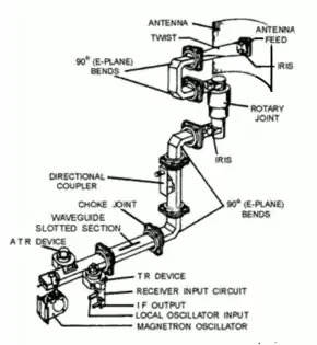
In a radar or satellite communications antenna the feed might consist of a feed horn, orthomode transducer, polarizer, frequency diplexer, waveguide, waveguide switches, rotary joint, etc.
Importance of matching
Particularly with a transmitting antenna, the antenna feed is a critical component that must be adjusted to function compatibly with the antenna and transmitter.
Each type of transmission line and each type of antenna has a specific characteristic impedance, which is the ratio of voltage to current that is the "favorite" of the antenna, or line, or radio. Typically the impedances of radios and feedlines are constant.[lower-alpha 3] Antenna impedances, however, swing by factors well over 1000:1, with changing frequency, as the antenna passes through an almost evenly-spaced sequence of resonances and "anti-"resonances at different frequencies.[lower-alpha 4]
The line impedance must be matched to the impedance of the antenna at one end and the transmitter at the other to efficiently transfer power between the transmitter and its antenna. If the impedances at either end of the line do not match, it will cause a condition called "standing waves" on the feed line, in which the RF energy is reflected back toward the transmitter, wasting energy and possibly overheating the transmitter.
The impedance is matched through a device called an antenna tuner or matching network, which can be in the transmitter, next to the transmitter, near the antenna, on the antenna, or any combination, including none. The degree of mismatch between the feedline and the antenna is measured by an instrument called an SWR meter (standing wave ratio meter), which measures the standing wave ratio (SWR) on the line: The ratio of the adjacent maximum and minimum voltage amplitudes, or adjacent maximum and minimum current amplitudes.[lower-alpha 5]
See also
Notes
- Although beam antennas are common, the passive elements don't have to specifically radiate a beam; they can form some other desired radiation pattern, for example, low-angle omnidirectional radiation for long-distance skywave propagation.
- The first amplifier in a receiver is called (among other names) the RF front end, the low-noise block converter (LNB), or low noise amplifier (LNA).
- Only the rate of power loss in transmission lines noticeably changes with frequency: The ratio of voltage to current remains constant, even as the power-loss piles up. Feedline impedances are essentially constant for all frequencies up to a very high cut-off frequency far above HF and VHF, where the wavelength becomes ~10× the spacing between the conductors in the line, or smaller.
- Antennas with many different-sized elements can have multiple intermeshed sequences of resonances. The same issue arises if different-sized metal objects are close enough to the antenna or the feedline to couple inductively with either.
- The max/min current ratio is identical to the max/min voltage ratio, so there is no difference between the values of "voltage standing wave ratio" (VSWR) and "current standing wave ratio" (ISWR), other than the technicalities of how the measurement is made.
References
- Silver, H. Ward (N0AX), ed. (2011). The ARRL Antenna Book (22 ed.). Newington, CT: American Radio Relay League. ISBN 978-0-87259-680-1.
| Activities |  | ||||||
|---|---|---|---|---|---|---|---|
| Culture | |||||||
| Governance | |||||||
| Modes of communication |
| ||||||
| Technologies | |||||||
| Related | |||||||