Expansion joint
An expansion joint or movement joint is an assembly designed to hold parts together while safely absorbing temperature-induced expansion and contraction of building materials, and vibration, or to allow movement due to ground settlement or seismic activity. They are commonly found between sections of buildings, bridges, sidewalks, railway tracks, piping systems, ships, and other structures.

Building faces, concrete slabs, and pipelines expand and contract due to warming and cooling from seasonal variation, or due to other heat sources. Before expansion joint gaps were built into these structures, they would crack under the stress induced.
Bridge expansion joints
Bridge expansion joints are designed to allow for continuous traffic between structures while accommodating movement, shrinkage, and temperature variations on reinforced and prestressed concrete, composite, and steel structures. They stop the bridge from bending out of place in extreme conditions, and also allow enough vertical movement to permit bearing replacement [1] without the need to dismantle the bridge expansion joint. There are various types, which can accommodate movement from 30 to 1,000 millimetres (1.2 to 39.4 in). They include joints for small movement (EMSEAL BEJS, XJS, JEP, WR, WOSd, and Granor AC-AR), medium movement (ETIC EJ, Wd), and large movement (WP, ETIC EJF/Granor SFEJ).
Modular expansion joints are used when the movements of a bridge exceed the capacity of a single gap joint or a finger type joint. A watertight system, invented by the Swiss company Mageba, is designed on a modular basis and can be tailored to satisfy the specific requirements of almost any structure.[2][3][4] Modular multiple-gap expansion joints can accommodate movements in every direction and rotations about every axis. They can be used for longitudinal movements of as little as 160 mm, or for very large movements of well over 3000 mm. The total movement of the bridge deck is divided among a number of individual gaps which are created by horizontal surface beams. The individual gaps are sealed by watertight elastomeric profiles, and surface beam movements are regulated by an elastic control system. The drainage of the joint is via the drainage system of the bridge deck. Certain joints feature so-called “sinus plates” on their surface, which reduce noise from over-passing traffic by up to 80%.[5]
See also masonry control joints, which are sometimes used in bridge slabs.
Masonry
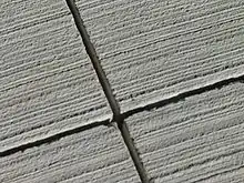
Clay bricks expand as they absorb heat and moisture. This places compression stress on the bricks and mortar, encouraging bulging or flaking.[6] A joint replacing mortar with elastomeric sealant will absorb the compressive forces without damage.[7] Concrete decking (most typically in sidewalks) can suffer similar horizontal issues, which is usually relieved by adding a wooden spacer between the slabs. The wooden expansion joint compresses as the concrete expands. Dry, rot-resistant cedar is typically used, with a row of nails sticking out that will embed into the concrete and hold the spacer in place.[8]
Comparison to control joints

Control joints, or contraction joints, are sometimes confused with expansion joints, but have a different purpose and function. Concrete and asphalt have relatively weak tensile strength, and typically form random cracks as they age, shrink, and are exposed to environmental stresses (including stresses of thermal expansion and contraction). Control joints attempt to attenuate cracking by designating lines for stress relief. They are cut into pavement at regular intervals. Cracks tend to form along the cuts, rather than in random fashion elsewhere. This is primarily an aesthetic issue; the appearance of even, regular cracking, which may be hidden in the joint’s crevice, is often preferred over random cracking.[9]
Thus, expansion joints reduce cracks, including in the overall structure, while control joints manage cracks, primarily along the visual surface.
Roadway control joints may be sealed with hot tar, cold sealant (such as silicone), or compression sealant (such as rubber or polymers based crossed linked foams).[10] Mortar with a breakaway bond may be used to fill some control joints.
Control joints must have adequate depth and not exceed maximum spacing for them to be effective. Typical specifications for a four-inch-thick slab are:[11]
- 25% depth of material
- spacing at 24x to 36x of slab depth (some specification call for a maximum of 30x)
- special care for inside corners
Railway expansion joints

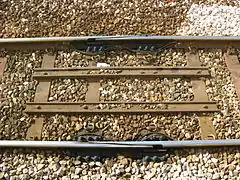
If a railway track runs over a bridge which has expansion joints that move more than a few millimeters, the track must be able to compensate this longer expansion or contraction. On the other hand, the track must always provide a continuous surface for the wheels traveling over it. These conflicting requirements are served by special expansion joints, where two rails glide along each other at a very acute angle during expansion or contraction. They are typically seen near one or both ends of large steel bridges. Such an expansion joint looks somewhat like the tongue of a railroad switch, but with a different purpose and operation.
Ducted air systems
Expansion joints are required in large ducted air systems to allow fixed pieces of piping to be largely free of stress as thermal expansion occurs. Bends in elbows also can accommodate this. Expansion joints also isolate pieces of equipment such as fans from the rigid ductwork thereby reducing vibration to the ductwork as well as allowing the fan to “grow” as it comes up to the operating air system temperature without putting stress on the fan or the fixed portions of ductwork.
An expansion joint is designed to allow deflection in the axial (compressive), lateral (shear), or angular (bending) deflections. Expansion joints can be non-metallic or metallic (often called bellows type). Non-metallic can be a single ply of rubberized material or a composite made of multiple layers of heat and erosion resistant flexible material. Typical layers are: outer cover to act a gas seal, a corrosion-resistant material such as Teflon, a layer of fiberglass to act as an insulator and to add durability, several layers of insulation to ensure that the heat transfer from the flue gas is reduced to the required temperature and an inside layer.
A bellows is made up of a series of one or more convolutions of metal to allow the axial, lateral, or angular deflection.
Pipe expansion joints

.jpg.webp)
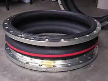
Pipe expansion joints are necessary in systems that convey high temperature substances such as steam or exhaust gases, or to absorb movement and vibration. A typical joint is a bellows of metal (most commonly stainless steel), plastic (such as PTFE), fabric (such as glass fibre) or an elastomer such as rubber. A bellows is made up of a series of convolutions, with the shape of the convolution designed to withstand the internal pressures of the pipe, but flexible enough to accept axial, lateral, and angular deflections. Expansion joints are also designed for other criteria, such as noise absorption, anti-vibration, earthquake movement, and building settlement. Metal expansion joints have to be designed according to rules laid out by EJMA, for fabric expansion joints there are guidelines and a state-of-the-art description by the Quality Association for Fabric Expansion Joints. Pipe expansion joints are also known as "compensators", as they compensate for the thermal movement.
Pressure balanced expansion joints
Expansion joints are often included in industrial piping systems to accommodate movement due to thermal and mechanical changes in the system. When the process requires large changes in temperature, metal components change size. Expansion joints with metal bellows are designed to accommodate certain movements while minimizing the transfer of forces to sensitive components in the system.
Pressure created by pumps or gravity is used to move fluids through the piping system. Fluids under pressure occupy the volume of their container. The unique concept of pressure balanced expansion joints is they are designed to maintain a constant volume by having balancing bellows compensate for volume changes in the bellows (line bellows) which is moved by the pipe. An early name for these devices was “pressure-volumetric compensator”.[12]
Manufacturing of rubber expansion joints
Wrapping fabric reinforced rubber sheets
Rubber expansion joints are mainly manufactured by manual wrapping of rubber sheets and fabric reinforced rubber sheets around a bellows-shaped product mandrel. Besides rubber and fabric, reinforced rubber and/or steel wires or metal rings are added for additional reinforcement.[13] After the entire product is built up on the mandrel, it is covered with a winding of (nylon) peel ply to pressurize all layers together. Because of the labor-intensive production process, a large part of the production has moved to eastern Europe and Asian countries.
Molded rubber expansion joints
Some types of rubber expansion joints are made with a molding process. Typical joints that are molded are medium-sized expansion joints with bead rings, which are produced in large quantities. These rubber expansion joints are manufactured on a cylindrical mandrel, which is wrapped with bias cut fabric ply. At the end the bead rings are positioned and the end sections are folded inwards over the bead rings. This part is finally placed in a mold and molded into shape and vulcanized. This is a highly automated solution for large quantities of the same type of joint.
Automated winding of rubber expansion joints
New technology has been developed to wind rubber and reinforcement layers on the (cylindrical or bellows-shaped) mandrel automatically using industrial robots instead of manual wrapping. This is fast and accurate and provides repeatable high quality. Another aspect of using industrial robots for the production of rubber expansion joints is the possibility to apply an individual reinforcement layer instead of using pre-woven fabric. The fabric reinforcement is pre-woven and cut at the preferred bias angle. With individual reinforcement it is possible to add more or less fiber material at different sections of the product by changing the fiber angles over the length of the product.[14]
Expansion joint accessories
Liners
Internal liners can be used to either protect the metallic bellows from erosion or reduce turbulence across the bellows. They must be used when purge connectors are included in the design. In order to provide enough clearance in the liner design, appropriate lateral and angular movements must be specified by the designer. When designing an expansion joint with combination ends, flow direction must be specified as well.[15]
Covers
External covers or shrouds should be used to protect the internal bellows from being damaged. They also serve a purpose as insulation of the bellows. Covers can either be designed as removable or permanent accessories.[16]
Particulate barriers/purge connectors
In systems that have a media with significant particulate content (i.e. flash or catalyst), a barrier of ceramic fiber can be utilized to prevent corrosion and restricted bellows flexibility resulting from the accumulation of the particulate. Purge connectors may also be utilized to perform this same function. Internal liners must also be included in the design if the expansion joint includes purge connectors or particulate barriers.[17]
Limit rods
Limit rods may be used in an expansion joint design to limit the axial compression or expansion. They allow the expansion joint to move over a range according to where the nut stops are placed along the rods. Limit rods are used to prevent bellows over-extension while restraining the full pressure thrust of the system.
Failure modes
Expansion joint failure can occur for various reasons, but experience shows that failures falls into several distinct categories. This list includes, but is not limited to: shipping and handling damage, improper installation/insufficient protection, during/after installation, improper anchoring, guiding, and supporting of the system, anchor failure in service, corrosion, system over-pressure, excessive bellows deflection, torsion, bellows erosion, and particulate matter in bellows convolutions restricting proper movement.[18]
There are various actions that can be taken to prevent and minimize expansion joint failure. During installation, prevent any damage to the bellows by carefully following the instructions furnished by the manufacturer.[19] After installation, carefully inspect the entire piping system to see if any damage occurred during installation, if the expansion joint is in the proper location, and if the expansion joint flow direction and positioning is correct.[20] Also, periodically inspect the expansion joint throughout the operating life of the system in order to check for external corrosion, loosening of threaded fasteners and deterioration of anchors, guides, and other hardware.[21]
Other expansion joint types
Other types of expansion joints can include: fabric expansion joint, metal expansion joint (Pressure balanced expansion joints are a type of Metal expansion joints), toroidal expansion joint, gimbal expansion joint, universal expansion joint, in-line expansion joint, refractory lined expansion joint, hinged expansion joint, reinforced expansion joint and more.
Copper expansion joints are excellent materials designed for the movement of building components due to temperature, loads, and settlement. Copper is easy to form and lasts a long time. Details regarding roof conditions, roof edges, floors, are available.[22]
See also
References
- Freyssinet: Bearing Replacement Archived 2012-04-26 at the Wayback Machine, Freyssinet Ltd. (retrieved 22 December 2011)
- Freyssinet: CIPEC Bridge Expansion Joints Archived 2012-04-06 at the Wayback Machine, Freyssinet Ltd. (retrieved 21 December 2011)
- EMSEAL: BEJS Expansion Joint System, EMSEAL Joint Systems. (retrieved 8 August 2013)
- Britflex BEJ Expansion Joint, Universal Sealants UK Ltd. (retrieved 27 April 2015)
- Modular expansion joint
- "TECHNICAL NOTES on Brick Construction TN 18A Accommodating Expansion of Brickwork" (PDF). Brick Industry Association. Retrieved 2018-05-25.
- "Difference Between Control and Expansion Joints". www.masonryconstruction.com. Archived from the original on 2016-08-25. Retrieved 2018-01-23.
- "Fix those rotted, wood concrete patio dividers | HeraldNet.com". HeraldNet.com. 2009-09-09. Retrieved 2018-01-23.
- "Placing Joints in Concrete Flatwork- Why, How, and When". www.cement.org. Retrieved 2018-01-23.
- Expansion Joint Filler boards' properties/features and applications
- "Placing Control Joints in Concrete – The Concrete Network". www.concretenetwork.com. Retrieved 2018-01-23.
- Technical Bulletin: Pressure Balanced Expansion Joints, U.S. Bellows, Inc. (retrieved 31 August 2010)
- "Elastomeric Expansion Joint Components". Gallagher Fluid Seals. Retrieved 21 July 2017.
- TANIQ: automated winding of rubber joints Archived 2011-07-16 at the Wayback Machine, TANIQ(retrieved 6 December 2010)
- U.S. Bellows Catalog: Internal Liner, U.S. Bellows, Inc. (retrieved 31 August 2010)
- U.S. Bellows Catalog: Protective Cover, U.S. Bellows, Inc. (retrieved 31 August 2010)
- U.S. Bellows Catalog: Purge Connector, U.S. Bellows, Inc. (retrieved 31 August 2010)
- Typical Causes of Expansion Joint Failure U.S. Bellows, (retrieved February 2012)
- Installation U.S. Bellows, (retrieved February 2012)
- Post Installation Inspection Prior to System Pressure Test U.S. Bellows, (retrieved February 2012)
- Periodic In-Service Inspection U.S. Bellows, (retrieved February 2012)]
- Building expansion joints, Copper in Architecture Design Handbook, Copper Development Association Inc., http://www.copper.org/applications/architecture/arch_dhb/building_expansion/intro.html