M.2
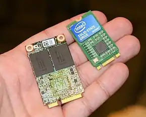
M.2, formerly known as the Next Generation Form Factor (NGFF), is a specification for internally mounted computer expansion cards and associated connectors. M.2 replaces the mSATA standard, which uses the PCI Express Mini Card physical card layout and connectors. Employing a more flexible physical specification, the M.2 allows different module widths and lengths, and, paired with the availability of more advanced interfacing features, makes the M.2 more suitable than mSATA in general for solid-state storage applications, and particularly in smaller devices such as ultrabooks and tablets.[1][2][3]
Computer bus interfaces provided through the M.2 connector are PCI Express 4.0 (up to four lanes), Serial ATA 3.0, and USB 3.0 (a single logical port for each of the latter two). It is up to the manufacturer of the M.2 host or module to select which interfaces are to be supported, depending on the desired level of host support and device type. The M.2 connector keying notches denote various purposes and capabilities of both M.2 hosts and devices. The unique key notches of M.2 modules also prevent them from being inserted into incompatible host connectors.[1][2][4]
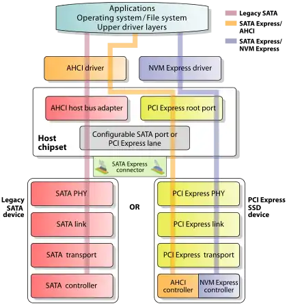
The M.2 specification supports NVM Express (NVMe) as the logical device interface for M.2 PCI Express SSDs, in addition to supporting legacy Advanced Host Controller Interface (AHCI) at the logical interface level. While the support for AHCI ensures software-level backward compatibility with legacy SATA devices and legacy operating systems, NVM Express is designed to fully utilize the capability of high-speed PCI Express storage devices to perform many I/O operations in parallel.[1]:14[5]
Features
Buses exposed through the M.2 connector are PCI Express 3.0 & newer, Serial ATA (SATA) 3.0 and USB 3.0, all these standards are backward compatible. As a result, M.2 modules can integrate multiple functions, including the following device classes: Wi-Fi, Bluetooth, satellite navigation, near field communication (NFC), digital radio, WiGig, wireless WAN (WWAN), and solid-state drives (SSDs).[6] The SATA revision 3.2 specification, in its gold revision as of August 2013, standardizes the M.2 as a new format for storage devices and specifies its hardware layout.[1]:12[7]
The M.2 specification provides up to four PCI Express lanes and one logical SATA 3.0 (6 Gbit/s) port, and exposes them through the same connector so both PCI Express and SATA storage devices may exist in the form of M.2 modules. Exposed PCI Express lanes provide a pure PCI Express connection between the host and storage device, with no additional layers of bus abstraction.[8] PCI-SIG M.2 specification, in its revision 1.0 as of December 2013, provides detailed M.2 specifications.[1]:12[9]
Storage interfaces
Three options are available for the logical device interfaces and command sets used for interfacing with M.2 storage devices, which may be used depending on the type of M.2 storage device and available operating system support:[1]:14[5][8]
- Legacy SATA
- Used for SATA SSDs, and interfaced through the AHCI driver and legacy SATA 3.0 (6 Gbit/s) port exposed through the M.2 connector.
- PCI Express using AHCI
- Used for PCI Express SSDs and interfaced through the AHCI driver and provided PCI Express lanes, providing backward compatibility with widespread SATA support in operating systems at the cost of performance. AHCI was developed when the purpose of a host bus adapter (HBA) in a system was to connect the CPU/memory subsystem with a much slower storage subsystem based on rotating magnetic media; as a result, AHCI has some inherent inefficiencies when applied to SSD devices, which behave much more like RAM than like spinning media.
- PCI Express using NVMe
- Used for PCI Express SSDs and interfaced through the NVMe driver and provided PCI Express lanes, as a high-performance and scalable host controller interface designed and optimized especially for interfacing with PCI Express SSDs. NVMe has been designed from the ground up, capitalizing on the low latency and parallelism of PCI Express SSDs, and complementing the parallelism of contemporary CPUs, platforms and applications. At a high level, primary advantages of NVMe over AHCI relate to NVMe's ability to exploit parallelism in host hardware and software, based on its design advantages that include data transfers with fewer stages, greater depth of command queues, and more efficient interrupt processing.
Form factors and keying
The M.2 standard has been designed as a revision and improvement to the mSATA standard, with the possibility of larger printed circuit boards (PCBs) as one of its primary incentives. While the mSATA took advantage of the existing PCI Express Mini Card (Mini PCIe) form factor and connector, M.2 has been designed from the ground up to maximize usage of the PCB space while minimizing the module footprint. As the result of the M.2 standard allowing longer modules and double-sided component population, M.2 SSD devices can provide larger storage capacities and can also double the storage capacity within the footprints of mSATA devices.[1]:20,22–23[3][11]
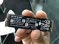
M.2 modules are rectangular, with an edge connector on one side (75 positions with up to 67 pins, 0.5 mm pitch, pins on opposing sides of the PCB are offset from each other), and a semicircular mounting hole at the center of the opposite edge. Each pin on the connector is rated for up to 50 V and 0.5 A, while the connector itself is specified to endure 60 mating cycles.[12]:6 The M.2 standard allows module widths of 12, 16, 22 and 30 mm, and lengths of 16, 26, 30, 38, 42, 60, 80 and 110 mm. Initial line-up of the commercially available M.2 expansion cards is 22 mm wide, with varying lengths of 30, 42, 60, 80 and 110 mm.[2][4][12][13] M.2 module codes contain both the width and length of a particular module; for example, 2242 as a module code means that the module is 22 mm wide and 42 mm long, while 2280 denotes a module 22 mm wide and 80 mm long.
An M.2 module is installed into a mating connector provided by the host's circuit board, and a single mounting screw secures the module into place. Components may be mounted on either side of the module, with the actual module type limiting how thick the components can be; the maximum allowable thickness of components is 1.5 mm per side, the board itself being 0.8-mm ± 10% thick.[9] Different host-side connectors are used for single- and double-sided M.2 modules, providing different amounts of space between the M.2 expansion card and the host's PCB.[3][4][12] Circuit boards on the hosts are usually designed to accept multiple lengths of M.2 modules, which means that the sockets capable of accepting longer M.2 modules usually also accept shorter ones by providing different positions for the mounting screw.[14][15]
| Key ID |
Notched pins |
Provided interfaces |
|---|---|---|
| A | 8–15 | 2x PCIe ×1, USB 2.0, I2C and DP ×4 |
| B | 12–19 | PCIe ×2, SATA, USB 2.0 and 3.0, audio, UIM, HSIC, SSIC, I2C and SMBus |
| C | 16–23 | Reserved for future use |
| D | 20–27 | |
| E | 24–31 | 2x PCIe ×1, USB 2.0, I2C, SDIO, UART and PCM |
| F | 28–35 | Future Memory Interface (FMI) |
| G | 39–46 | Reserved for custom use (unused in the M.2 specification) |
| H | 43–50 | Reserved for future use |
| J | 47–54 | |
| K | 51–58 | |
| L | 55–62 | |
| M | 59–66 | PCIe ×4, SATA and SMBus |
| Type ID |
Top side | Bottom side |
|---|---|---|
| S1 | 1.20 mm | — |
| S2 | 1.35 mm | — |
| S3 | 1.50 mm | — |
| D1 | 1.20 mm | 1.35 mm |
| D2 | 1.35 mm | 1.35 mm |
| D3 | 1.50 mm | 1.35 mm |
| D4 | 1.50 mm | 0.70 mm |
| D5 | 1.50 mm | 1.50 mm |
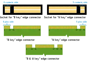
The PCB of an M.2 module provides a 75-position edge connector; depending on the type of module, certain pin positions are removed to present one or more keying notches. Host-side M.2 connectors (sockets) may populate one or more mating key positions, determining the type of modules accepted by the host; as of April 2014, host-side connectors are available with only one mating key position populated (either B or M).[4][12][10] Furthermore, M.2 sockets keyed for SATA or two PCI Express lanes (PCIe ×2) are referred to as "socket 2 configuration" or "socket 2", while the sockets keyed for four PCI Express lanes (PCIe ×4) are referred to as "socket 3 configuration" or "socket 3".[1]:15[19]
For example, M.2 modules with two notches in B and M positions use up to two PCI Express lanes and provide broader compatibility at the same time, while the M.2 modules with only one notch in the M position use up to four PCI Express lanes; both examples may also provide SATA storage devices. Similar keying applies to M.2 modules that utilize provided USB 3.0 connectivity.[4][10][20]
Various types of M.2 devices are denoted using the "WWLL-HH-K-K" or "WWLL-HH-K" naming schemes, in which "WW" and "LL" specify the module width and length in millimeters, respectively. The "HH" part specifies, in an encoded form, whether a module is single- or double-sided, and the maximum allowed thickness of mounted components; possible values are listed in the right table above. Module keying is specified by the "K-K" part, in an encoded form using the key IDs from the left table above; it can also be specified as "K" only, if a module has only one keying notch.[4][12]
Beside socketed modules, the M.2 standard also includes the option for having permanently soldered single-sided modules.[12]
References
- Jim Handy; Jon Tanguy; Jaren May; David Akerson; Eden Kim; Tom Coughlin (September 20, 2014). "SNIA Webcast: All About M.2 SSDs" (PDF). SNIA. Retrieved July 15, 2015.
- "SATA M.2 Card". SATA-IO. Retrieved September 14, 2013.
- Mark Kyrnin. "What Is M.2? New Interface and Form Factor For Compact SSD Drives in Laptops and Desktops". compreviews.about.com. Retrieved July 15, 2015.
- "M.2 Connector (NGFF) Introduction" (PDF). orvem.eu. ATTEND. Archived from the original (PDF) on February 3, 2014. Retrieved January 17, 2014.
- Dave Landsman (August 9, 2013). "AHCI and NVMe as Interfaces for SATA Express Devices – Overview" (PDF). SATA-IO. Retrieved July 15, 2015.
- "SATA-IO FAQ: What is the M.2 card and what is the status of the specification?" (PDF). SATA-IO. August 8, 2013. p. 2. Retrieved July 15, 2015.
- "Serial ATA Revision 3.2 (Gold Revision)" (PDF). knowledgetek.com. SATA-IO. August 7, 2013. pp. 194–209. Archived from the original (PDF) on March 27, 2014. Retrieved July 15, 2015.
- Paul Wassenberg (June 19, 2013). "SATA Express: PCIe Client Storage" (PDF). SATA-IO. Retrieved October 2, 2013.
- "PCI Express M.2 Specification Revision 1.0". PCI-SIG. 2013. Retrieved December 14, 2013.
- Marshall R. (April 7, 2014). "Buying an M.2 SSD? How to tell which is which?". Republic of Gamers. Asus. Archived from the original on April 27, 2014. Retrieved April 28, 2014.
- "M.2 Frequently Asked Questions". Kingston Technology. Retrieved July 15, 2015.
- "M.2 (NGFF) Quick Reference Guide" (PDF). Tyco Electronics. Retrieved November 16, 2013.
- "Intel SSD 530 Series Arriving Next Week – Feature NGFF M.2 Interface". wccftech.com. Retrieved September 14, 2013.
- "M2P4S M.2 (NGFF) PCIe base SSD to PCIe ×4 Adapter". hwtools.net. February 14, 2014. Retrieved June 22, 2014.
- John Burek (April 14, 2015). "2015 Guide: The Best M.2 Solid-State Drives". computershopper.com. Retrieved July 15, 2015.
- "SMBus interface for SSD Socket 2 and Socket 3 (PCI-SIG engineering change notice)" (PDF). PCI-SIG. August 11, 2014. p. 2. Archived from the original (PDF) on July 14, 2015. Retrieved August 5, 2015.
- "How to distinguish the differences between M.2 cards | Dell US". www.dell.com. Retrieved March 24, 2020.
- "PCI Express M.2 Specification, Revision 1.0" (PDF). PCI-SIG. November 1, 2013. p. 23. Retrieved June 13, 2020.
- Jack Zhang; Mark Liang (July 4, 2015). "NVM Express Based Solid-State Drives: Crossing the Chasm, Going Mainstream" (PDF). Intel. p. 39. Retrieved August 27, 2015.
- Les Tokar (November 24, 2013). "Understanding M.2 NGFF SSD standardization (or the lack of)". thessdreview.com. Retrieved April 28, 2014.
External links
| Wikimedia Commons has media related to M.2. |
- Official Serial ATA International Organization (SATA-IO) website
- Official Peripheral Component Interconnect Special Interest Group (PCI-SIG) website
- Understanding M.2, the interface that will speed up your next SSD, Ars Technica, February 9, 2015, by Andrew Cunningham
- LFCS: Preparing Linux for nonvolatile memory devices, LWN.net, April 19, 2013, by Jonathan Corbet
- PCIe SSD 101: An Overview of Standards, Markets and Performance, SNIA, August 2013, archived from the original on February 2, 2014
- Interface card mount – US patent 20130294023, November 7, 2013, assigned to Raphael Gay
| General | |
|---|---|
| Standards |
|
| Storage | |
| Peripheral | |
| Audio | |
| Portable | |
| Embedded | |
Interfaces are listed by their speed in the (roughly) ascending order, so the interface at the end of each section should be the fastest. | |
| Key terminology | |||||
|---|---|---|---|---|---|
| Flash manufacturers | |||||
| Controllers |
| ||||
| SSD manufacturers | |||||
| Interfaces |
| ||||
| Configurations | |||||
| Related organizations | |||||
| |||||