Submersible pump
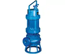
A submersible pump (or sub pump, electric submersible pump (ESP)) is a device which has a hermetically sealed motor close-coupled to the pump body. The whole assembly is submerged in the fluid to be pumped. The main advantage of this type of pump is that it prevents pump cavitation, a problem associated with a high elevation difference between pump and the fluid surface. Submersible pumps push fluid to the surface as opposed to jet pumps which create a vacuum and rely upon atmospheric pressure. Submersibles use pressurised fluid from the surface to drive a hydraulic motor downhole, rather than an electric motor, and are used in heavy oil applications with heated water as the motive fluid.
History
Ca. 1928 Armenian oil delivery system engineer and inventor Armais Arutunoff successfully installed the first submersible oil pump in an oil field.[1] In 1929, Pleuger Pumps (today Pleuger Industries) pioneered the design of the submersible turbine pump, the forerunner of the modern multi-stage submersible pump.[2]
Working principle
Electric submersible pumps are multistage centrifugal pumps operating in a vertical position. Liquids, accelerated by the impeller, lose their kinetic energy in the diffuser where a conversion of kinetic to pressure energy takes place. This is the main operational mechanism of radial and mixed flow pumps. In the HSP, the motor is a hydraulic motor rather than an electrical motor, and may be closed cycle (keeping the power fluid separate from the produced fluid) or open cycle (mingling the power fluid with produced fluid downhole, with surface separation).
The pump shaft is connected to the gas separator or the protector by a mechanical coupling at the bottom of the pump. Fluids enter the pump through an intake screen and are lifted by the pump stages. Other parts include the radial bearings (bushings) distributed along the length of the shaft providing radial support to the pump shaft. An optional thrust bearing takes up part of the axial forces arising in the pump but most of those forces are absorbed by the protector's thrust bearing.
There are also screw-type submersible pumps, there is a steel screw which is used as a working element in them. The screw allows the pump to work in water with a high sand content and other mechanical impurities.
Applications
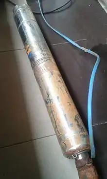
Submersible pumps are found in many applications. Single stage pumps are used for drainage, sewage pumping, general industrial pumping and slurry pumping. They are also popular with pond filters. Multiple stage submersible pumps are typically lowered down a borehole and most typically used for residential, commercial, municipal and industrial water extraction (abstraction), water wells and in oil wells.
Other uses for submersible pumps include sewage treatment plants, seawater handling, fire fighting (since it is flame retardant cable), water well and deep well drilling, offshore drilling rigs, artificial lifts, mine dewatering, and irrigation systems.
Pumps in electrical hazardous locations used for combustible liquids or for water that may be contaminated with combustible liquids must be designed not to ignite the liquid or vapors.
Use in oil wells
Submersible pumps are used in oil production to provide a relatively efficient form of "artificial lift", able to operate across a broad range of flow rates and depths.[3][4] By decreasing the pressure at the bottom of the well (by lowering bottomhole flowing pressure, or increasing drawdown), significantly more oil can be produced from the well when compared with natural production. The pumps are typically electrically powered, referred to as Electrical Submersible Pumps (ESP) or if hydraulically powered, referred to as Hydraulic Submersible Pumps, (HSP).
ESP systems consist of both surface components (housed in the production facility, for example an oil platform) and sub-surface components (found in the well hole). Surface components include the motor controller (often a variable speed controller), surface cables and transformers. The subsurface components are deployed by attaching to the downhole end of a tubing string, while at the surface, and then lowered into the wellbore along with the tubing.
A high-voltage (3 to 5 kV) alternating-current source at the surface drives the subsurface motor. Until recently, ESPs had been costly to install due to the requirement of an electric cable extending from the source to the motor. This cable had to be wrapped around jointed tubing and connected at each joint. New coiled tubing umbilicals allow for both the piping and electric cable to be deployed with a single conventional coiled tubing unit. Cables for sensor and control data may also be included.
The subsurface components generally include a pump portion and a motor portion, with the motor downhole from the pump. The motor rotates a shaft that, in turn, rotates pump impellers to lift fluid through production tubing to the surface. These components must reliably work at high temperatures of up to 300 °F (149 °C) and high pressures of up to 5,000 psi (34 MPa), from deep wells of up to 12,000 feet (3.7 km) deep with high energy requirements of up to 1000 horsepower (750 kW). The pump itself is a multi-stage unit with the number of stages being determined by the operating requirements. Each stage includes an impeller and diffuser. Each impeller is coupled to the rotating shaft and accelerates fluid from near the shaft radially outward. The fluid then enters a non-rotating diffuser, which is not coupled to the shaft and contains vanes that direct fluid back toward the shaft. Pumps come in diameters from 90mm (3.5 inches) to 254mm (10 inches) and vary between 1 metre (3 ft) and 8.7 metres (29 ft) in length. The motor used to drive the pump is typically a three phase, squirrel cage induction motor, with a nameplate power rating in the range 7.5 kW to 560 kW (at 60 Hz).[3]
ESP assemblies may also include: seals coupled to the shaft between the motor and pump; screens to reject sand; and fluid separators at the pump intake that separate gas, oil and water.[3] ESPs have dramatically lower efficiencies with significant fractions of gas, greater than about 10% volume at the pump intake, so separating gas from oil prior to the pump can be important. Some ESPs include a water/oil separator which permits water to be re-injected downhole. As some wells produce up to 90% water and fluid lift is a significant cost, re-injecting water before lifting it to the surface can reduce energy consumption and improve economics Given ESPs' high rotational speed of up to 4000 rpm (67 Hz) and tight clearances, they are not very tolerant of solids such as sand.
There are at least 15 brands of oilfield ESPs used throughout the world.
Cables
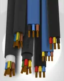
Submersible pump cable are designed for use in wet ground or under water, with types specialized for pump environmental conditions.[5][6][7]
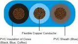
A submersible pump cable is a specialized product to be used for a submersible pump in a deep well, or in similarly harsh conditions. The cable needed for this type of application must be durable and reliable as the installation location and environment can be extremely restrictive as well as hostile. As such, submersible pump cable can be used in both fresh and salt water. It is also suitable for direct burial and within well castings. A submersible pump cable's area of installation is physically restrictive. Cable manufacturers must keep these factors in mind to achieve the highest possible degree of reliability. The size and shape of submersible pump cable can vary depending on the usage and preference and pumping instrument of the installer. Pump cables are made in single and multiple conductor types and may be flat or round in cross section; some types include control wires as well as power conductors for the pump motor. Conductors are often color-coded for identification and an overall cable jacket may also be color-coded.
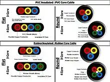
Major types of cable include:
In 3&4 Core cable as per right side SPC types image shown, plain Copper/Tinned Copper used as a conductor.
- PVC 3&4 Core Cable
- Flat Cable
- Round Cable
- Rubber 3&4 Core Cable
- Flat Cable
- Round Cable
- Flat Drincable
- HO7RN-F Cable
See also
References
- "A Historical Perspective of Oilfield Electrical Submersible Pump Industry". esppump.com. ESP pump.com. September 17, 2012. Retrieved November 16, 2017.
With three employees, Arutunoff built and installed the first ESP in an oil well in the El Dorado field near Burns, Kansas.
- "A brief history of pumps". worldpumps.com. Elsevier Ltd. March 23, 2009. Retrieved November 16, 2017.
1929: Pleuger pioneers the submersible turbine pump motor
- Lyons (ed), Standard Handbook of Petroleum & Natural Gas Engineering", p. 662
- Other forms of artificial lift include Gas Lift, Beam Pumping, Plunger Lift and Progressive cavity pump.
- "Submersible pump cable", The Pump Book, pp. 67–74, ISBN 978-0-615-18509-5
- Ray C. Mullin, Phil Simmons (2011), "Submersible Pump Cable", Electrical Wiring Residential, pp. 423–424, ISBN 978-1-4354-9826-6
- Robert J. Alonzo (19 January 2010). Electrical Codes, Standards, Recommended Practices and Regulations: An Examination of Relevant Safety Considerations. Elsevier. pp. 317–. ISBN 978-0-8155-2045-0. Retrieved 16 November 2012.
- Lyons, William C., ed. (1996). Standard Handbook of Petroleum & Natural Gas Engineering. 2 (6 ed.). Gulf Professional Publishing. ISBN 0-88415-643-5.
External links
- Operation, applications and advantages of electric submersible pumps
- Versatile Pump Works Under Water, July 1947, Popular Science excellent cutaway drawing of large public water works submersible pump design
| Wikimedia Commons has media related to Submersible pumps. |