Spiral antenna
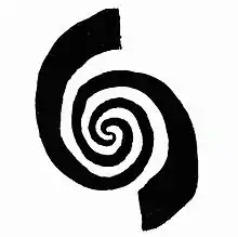
In microwave systems, a spiral antenna is a type of RF antenna. It is shaped as a two-arm spiral, or more arms may be used.[1](p 14‑2) Spiral antennas were first described in 1956.[2] Spiral antennas belong to the class of frequency independent antennas[3] which operate over a wide range of frequencies. Polarization, radiation pattern and impedance of such antennas remain unchanged over large bandwidth.[4] Such antennas are inherently circularly polarized with low gain. Array of spiral antennas can be used to increase the gain. Spiral antennas are reduced size antennas with its windings making it an extremely small structure. Lossy cavities[5] are usually placed at the back to eliminate back lobes because a unidirectional pattern is usually preferred in such antennas. Spiral antennas are classified into different types; Archimedean spiral, logarithmic spiral, square spiral, and star spiral, etc. Archimedean spiral is the most popular configuration.

Principles of Operation
In general, antennas may operate in three different modes: traveling wave, fast wave, and leaky wave. Spiral antennas use all three.
The traveling wave, formed on spiral arms, allows for broadband performance. Fast wave is due to mutual coupling phenomenon occurring between arms of spiral. Leaky wave “leaks” the energy during propagation through the spiral arms to produce radiation.
Ring theory (band theory) explains the working principle of spiral antenna. The theory states that spiral antenna radiates from an active region where the circumference of spiral equals the wavelength.[6]
Design
Different design parameters are to be considered while designing a square spiral antenna. The parameters include spacing between the turns , width of arm , inner radius and outer radius . The inner radius is measured from center of the spiral to center of the first turn while the outer radius is measured from center of the spiral to center of the outermost turn. Other than these design parameters, spiral antennas have lowest ( and highest operating frequencies. Here corresponds to speed of light in the metal of the antenna, mainly determined by the electrical permittivity of the substrate the spiral lies on, and its over-coating (if any).


In a polar coordinate system, the spiral grows along the -axis and -axis simultaneously. Often-used Archemedian spirals satisfy a particularly simple equation where corresponds to growth factor and corresponds to multiplication factor. The consequence is equal spacing between successive turns, which limits the width of the spiral arms, which is usually kept constant. Other choices of spiral shape can also be used, such as logarithmic spirals that satisfy ; the resulting spiral arms are more widely spaced in the outer turns, which can better accommodate arms that widen significantly.


Different designs of spiral antenna can be obtained by varying number of turns for each arm, the number of arms, the type of spiral, the spacing between its turns, the variation of the width of its arm(s), and the material(s) that surround it, such as the substrate it lies on.
Elements
The antenna usually has two conductive spiral arms, extending from the center outwards. The direction of rotation of the spiral defines the direction of antenna polarization. Additional spirals may be included as well, to form a multi-spiral structure. The antenna may be a flat disc, with conductors resembling a pair of loosely nested clock springs, or the spirals may extend in a three-dimensional shape like a screw thread.
The output of a two-arm or four-arm spiral antenna is a balanced line. If a single input or output line is desired – for example a grounded coaxial line – then a balun or other transformer is added to alter the signal’s electrical mode.
Usually the spiral is cavity-backed – that is, there is a cavity of air or non-conductive material or vacuum, surrounded by conductive walls behind the spiral. A cavity with the proper shape and size changes the antenna pattern to receive and transmit in a single direction, away from the cavity.
The spiral can be printed or etched over a specifically chosen dielectric medium, whose permittivity can be used to alter the frequency for a given size. Dielectric mediums like Rogers RT Duroid help in reducing the physical size of antenna. Thin substrates with higher permittivity can achieve the same result as thick substrates with lower permittivity. The only problem with such materials is their less availability and high costs.[7]
Applications
Spiral antennas transmit circularly polarized radio waves, and will receive linearly polarized waves in any orientation, but will drastically attenuate circularly polarized signals received with the opposite-rotation. A spiral antenna will reject circularly polarized waves of one type, while receiving perfectly well waves having the other polarization.
One application of spiral antennas is wide-band communications. Another application of spiral antennas is monitoring of the frequency spectrum. One antenna can receive over a wide bandwidth, for example a ratio 5:1 between the maximum and minimum frequency. Usually a pair of spiral antennas are used in this application, having identical parameters except the polarization, which is opposite (one is right-hand, the other left-hand oriented). Spiral antennas are useful for microwave direction-finding.[8]
References
- Johnson, Richard C.; Jasik, Henry, eds. (1961). Antenna Engineering Handbook (Second ed.). ISBN 0-07-032291-0.
- Orr, William I. (1976). Beam Antenna Handbook (5th ed.). Radio Publications. pp. 185–186.
- "Design and analysis of an UWB printed monopole antenna with Hilbert-curve fractal-shaped slots for multiple-band rejection functionality". IGI-Global.com. Frequency independent antennas.
- Mayes, Paul E. (1992). "Frequency-independent antennas and broad-band derivatives thereof". Proceedings of the IEEE. 80 (1): 103–112. doi:10.1109/5.119570.
- "Aperture-excitation of electrically-large, lossy cavities". National Institute of Standards and Technology (NIST).
- Mehta, A.; Mirshekar-Syahkal, D.; Nakano, H. (2006). "Beam adaptive single arm rectangular spiral antenna with switches". Microwaves, Antennas and Propagation (IEE Proceedings). 153 (1): –18. doi:10.1049/ip-map:20050045.
- Asad, M.; Gilani, J.; Khalid, A.; Iqbal, M.S. (2010). "Optimizing the Q factor of a square spiral antenna". PACCS: 227–230.
- Lipsky, Stephen E. (2004). Microwave Passive Direction Finding. SciTech Publishing. p. 40. ISBN 1-891121-23-5.
"Practical antenna" references
- "Spiral Antenna". Antenna Theory.