Helical antenna
A helical antenna is an antenna consisting of one or more conducting wires wound in the form of a helix. A helical antenna made of one helical wire, the most common type, is called monofilar, while antennas with two or four wires in a helix are called bifilar, or quadrifilar, respectively.
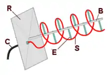
(B) Central support,
(C) Coaxial cable feedline,
(E) Insulating supports for the helix,
(R) Reflector ground plane,
(S) Helical radiating wire
In most cases, directional helical antennas are mounted over a ground plane, while omnidirectional designs may not be. The feed line is connected between the bottom of the helix and the ground plane. Helical antennas can operate in one of two principal modes — normal mode or axial mode.
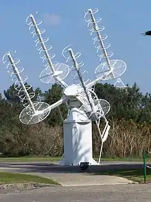
In the normal mode or broadside helical antenna, the diameter and the pitch of the aerial are small compared with the wavelength. The antenna acts similarly to an electrically short dipole or monopole, equivalent to a 1/4 wave vertical and the radiation pattern, similar to these antennas is omnidirectional, with maximum radiation at right angles to the helix axis. For monofilar designs the radiation is linearly polarized parallel to the helix axis. These are used for compact antennas for portable hand held as well as mobile vehicle mount two-way radios, and in larger scale for UHF television broadcasting antennas. In bifilar or quadrifilar implementations, broadside circularly polarized radiation can be realized.
In the axial mode or end-fire helical antenna, the diameter and pitch of the helix are comparable to a wavelength. The antenna functions as a directional antenna radiating a beam off the ends of the helix, along the antenna's axis. It radiates circularly polarized radio waves. These are used for satellite communication. Axial mode operation was discovered by physicist John D. Kraus[1]
Normal-mode helical
If the circumference of the helix is significantly less than a wavelength and its pitch (axial distance between successive turns) is significantly less than a quarter wavelength, the antenna is called a normal-mode helix. The antenna acts similar to a monopole antenna, with an omnidirectional radiation pattern, radiating equal power in all directions perpendicular to the antenna's axis. However, because of the inductance added by the helical shape, the antenna acts like a inductively loaded monopole; at its resonant frequency it is shorter than a quarter-wavelength long. Therefore, normal-mode helices can be used as electrically short monopoles, an alternative to center- or base-loaded whip antennas, in applications where a full sized quarter-wave monopole would be too big. As with other electrically short antennas, the gain, and thus the communication range, of the helix will be less than that of a full sized antenna. Their compact size makes "helicals" useful as antennas for mobile and portable communications equipment on the HF, VHF, and UHF bands.

The loading provided by the helix allows the antenna to be physically shorter than its electrical length of a quarter-wavelength. This means that for example a 1/4 wave antenna at 27MHz is 2.7 m (108”) long and is physically quite unsuitable for mobile applications. The reduced size of a helical provides the same radiation pattern in a much more compact physical size with only a slight reduction in signal performance.
An effect of using a helical conductor rather than a straight one is that the matching impedance is changed from the nominal 50 ohms to between 25 and 35 ohms base impedance. This does not seem to be adverse to operation or matching with a normal 50 ohm transmission line, provided the connecting feed is the electrical equivalent of a 1/2 wavelength at the frequency of operation.
Mobile HF helicals
Another example of the type as used in mobile communications is "spaced constant turn" in which one or more different linear windings are wound on a single former and spaced so as to provide an efficient balance between capacitance and inductance for the radiating element at a particular resonant frequency. Many examples of this type have been used extensively for 27 MHz CB radio with a wide variety of designs originating in the US and Australia in the late 1960s. To date many millions of these ‘helical antennas’ have been mass-produced for mainly mobile vehicle use and reached peak production during the CB Radio boom-times during the 1970s to late 1980s and used worldwide. Multi-frequency versions with manual plug-in taps have become the mainstay for multi-band single-sideband modulation (SSB) HF communications with frequency coverage over the whole HF spectrum from 1MHz to 30 MHz with from 2 to 6 dedicated frequency tap points tuned at dedicated and allocated frequencies in the land mobile, marine and aircraft bands. Recently these antennas have been superseded by electronicly tuned antenna matching devices. Most examples were wound with copper wire using a fiberglass rod as a former. The usually flexible or ridged radiator is then covered with a PVC or polyolefin heat-shrink tubing which provides a resilient and rugged waterproof covering for the finished mobile antenna. The fibreglass rod was then usually glued and/or crimped to a brass fitting and screw mounted onto an insulated base affixed to a vehicle roof, guard or bull-bar mount. This mounting provided a ground plane or reflector (provided by the vehicle) for an effective vertical radiation pattern.
These popular designs are still in common use as of 2018 and the ‘constant turn’ design originating in Australia have been universally adapted as standard FM receiving antennas for many factory produced motor vehicles as well as the existing basic style of aftermarket HF and VHF mobile helical. Another common use for broadside helixes is in the "rubber ducky antenna" found on most portable VHF and UHF radios using a steel or copper conductor as the radiating element and usually terminated to a BNC / TNC style or screw on connector for quick removal.
Helical broadcasting antennas
Specialized normal-mode helical antennas are used as transmitting antennas for FM radio and television broadcasting stations on the VHF and UHF bands.
Axial-mode helixical


When the helix circumference is near the wavelength of operation, the antenna operates in axial mode. This is a nonresonant traveling wave mode, in which instead of standing waves, the waves of current and voltage travel in one direction, up the helix. Instead of radiating linearly polarized waves normal to the antenna's axis, it radiates a beam of radio waves with circular polarisation along the axis, off the ends of the antenna. The main lobes of the radiation pattern are along the axis of the helix, off both ends. Since in a directional antenna only radiation in one direction is wanted, the other end of the helix is terminated in a flat metal sheet or screen reflector to reflect the waves forward.
In radio transmission, circular polarisation is often used where the relative orientation of the transmitting and receiving antennas cannot be easily controlled, such as in animal tracking and spacecraft communications, or where the polarisation of the signal may change, so end-fire helical antennas are frequently used for these applications. Since large helices are difficult to build and unwieldy to steer and aim, the design is commonly employed only at higher frequencies, ranging from VHF up to microwave.
The helix of the antenna can twist in two possible directions: right-handed or left-handed, the former having the same form as that of a common corkscrew. The 4-helix array in the first illustration uses left-handed helices, while all other illustrations show right-handed helices. In an axial-mode helical antenna the direction of twist of the helix determines the polarisation of the emitted wave. Two mutually incompatible conventions are in use for describing waves with circular polarisation, so the relationship between the handedness (left or right) of a helical antenna, and the type of circularly-polarized radiation it emits is often described in ways that appear to be ambiguous. However, Kraus (the inventor of the helical antenna) states "The left-handed helix responds to left-circular polarisation, and the right handed helix to right-circular polarisation (IEEE definition)".[2] The IEEE defines the sense of polarisation as "the sense of polarization, or handedness ... is called right handed (left handed) if the direction of rotation is clockwise (anti-clockwise) for an observer looking in the direction of propagation" [3] Thus a right-handed helix radiates a wave which is right-handed, the electric field vector rotating clockwise looking in the direction of propagation.
Helical antennas can receive signals with any type of linear polarisation, such as horizontal or vertical polarisation, but when receiving circularly polarized signals the handedness of the receiving antenna must be the same as the transmitting antenna; left-hand polarized antennas suffer a severe loss of gain when receiving right-circularly-polarized signals, and vice versa.
The dimensions of the helix are determined by the wavelength λ of the radio waves used, which depends on the frequency. In order to operate in axial-mode, the circumference should be equal to the wavelength.[4] The pitch angle should be 13 degrees, which is a pitch distance (distance between each turn) of 0.23 times the circumference, which means the spacing between the coils should be approximately one-quarter of the wavelength (λ/4). The number of turns in the helix determines how directional the antenna is: more turns improves the gain in the direction of its axis at both ends (or at 1 end when a ground plate is used), at a cost of gain in the other directions. When C<λ it operates more in normal mode where the gain direction is a donut shape to the sides instead of out the ends.
Terminal impedance in axial mode ranges between 100 and 200 ohms, approximately

where C is the circumference of the helix, and λ is the wavelength. Impedance matching (when C=λ) to standard 50 or 75 ohm coaxial cable is often done by a quarter wave stripline section acting as an impedance transformer between the helix and the ground plate.
The maximum directive gain is approximately:

where N is the number of turns and S is the spacing between turns. Most designs use C=λ and S=0.23*C, so the gain is typically G=3.45*N. In decibels, the gain is .

The half-power beamwidth is:

The beamwidth between nulls is:

The gain of the helical antenna strongly depends on the reflector.[6] The above classical formulas assume that the reflector has the form of a circular resonator (a circular plate with a rim) and the pitch angle is optimal for this type of reflector. Nevertheless, these formulas overestimate the gain for several dB.[7] The optimal pitch that maximizes the gain for a flat ground plane is in the range from 3° to 10° and it depends on the wire radius and antenna length.[7]
See also
References
- Proceedings of the I.R.E., March 1949, P.263
- Kraus, J.D. Antennas 2nd Ed, MacGraw Hill, 1988
- IEEE Std 149-1979 (R2008), "IEEE Standard Test Procedures for Antennas". Reaffirmed December 10, 2008, Approved December 15, 1977, IEEE-SA Standards Board. Approved October 9, 2003, American National Standards Institute. ISBN 0-471-08032-2. doi:10.1109/IEEESTD.1979.120310, sec. 11.1, p. 61.
- https://www.cv.nrao.edu/~demerson/helixgain/helix.htm
- Tomasi, Wayne (2004). Electronic Communication Systems - Fundamentals Through Advanced. Jurong, Singapore: Pearson Education SE Asia Ltd. ISBN 981-247-093-X.
- Djordjević, A.R., Zajić, A.G., and Ilić, M.M., “Enhancing the gain of helical antennas by shaping the ground conductor”, IEEE Antennas and Wireless Propagation Letters, Vol. 5, 2006, pp. 138-140
- Djordjević, A.R., Zajić, A.G., Ilić, M.M., and Stueber, G.L., “Optimization of helical antennas“, IEEE Antennas and Propagation Magazine, vol. 48, no. 6, December 2006, pp. 107-115
- General
- John D. Kraus and Ronald J. Marhefka, "Antennas: For All Applications, Third Edition", 2002, McGraw-Hill Higher Education
- Constantine Balanis, "Antenna Theory, Analysis and Design", 1982, John Wiley and Sons
- Warren Stutzman and Gary Thiele, "Antenna Theory and Design, 2nd. Ed.", 1998, John Wiley and Sons
External links
- Helical Antennas Antenna-Theory
- The Basics of Quadrifilar Helix Antennas by Bill Slade, Orban Microwave