Halo antenna
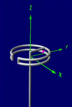
A halo antenna, or halo, is a 1⁄2 wavelength dipole antenna, which has been bent into a circle with an electrical break directly opposite the feed point. The dipole ends are close but do not meet, and may have an air capacitor between them to adjust the antenna's resonant frequency. If mounted horizontally, this antenna's radiation is approximately omnidirectional and horizontally polarized.
Halo antennas vs. loop antennas
This section contrasts halo antennas with loop antennas which are electrically dissimilar, but can be confused as they all share the same shape: a circle.
Halo vs. large loops
Although also a resonant antenna, the halo antenna is distinct from the resonant loop antenna, which is approximately double its size for the same operating frequency. In the case of the halo antenna, each half is about a quarter wavelength long and ends with a current node (and peak voltage) at the break. On the other hand, the two semi-circles of a resonant loop, each being a half wavelength long, end with a voltage node (opposite the feedpoint) but large current, where these semi-circles are connected. Resonant loops have a radiation pattern which peaks perpendicular to the loop (Z-axis, in the diagram) but falling to zero in the plane of the loop, quite opposite the radiation pattern of a halo antenna. Thus, despite the superficial similarity, these two antenna types are fundamentally unlike.
Halo vs. small loops
A halo antenna is distinct from the small-loop antenna in size,[lower-alpha 1] radiation pattern, radiation resistance, and efficiency. A halo antenna is a resonant antenna: Its feedpoint impedance is purely resistive at the design frequency. A small loop antenna, on the other hand, has lower radiation resistance and is not self-resonant; it requires some form of impedance matching to counter the loop's reactance (in practice, this usually consists of a shunt capacitor). Since the small antenna's radiation resistance is small, perhaps a few ohms at most, power converted to radio waves can be dwarfed by power lost by heat, due to resistance in the conductor. For better transmitting performance, larger antennas are always preferred, but at long wavelengths (lower MF and LF) the size of any resonant antenna (such as the halo) is unfeasibly large, and small loops are nevertheless used as a least-worst option.
The distribution of current along the two arms of a halo antenna is similar to the currents along the two arms (also a quarter wavelength long) of a half-wave dipole (see animation), being largest at the feedpoint and dropping to zero at the ends (the gap in the case of the halo). On the other hand, a small loop has a current which is approximately uniform and in‑phase along the conductor. The halo – again like the half-wave dipole – also has voltage peaks at the gap, whereas it is the larger current near the feedpoint most responsible for the radiation produced, with the antenna radiating slightly more towards the split in the loop. The small loop radiates nearly equally in all directions within the plane of the conductor.
Both the halo and small loops’ radiation patterns are opposite that of the full-wave loop, being maximum in the plane of the loop, rather than perpendicular to it; halo antennas radiate only a small amount perpendicular to the loop plane, and small loops have no perpendicular radiation at all (“null”).
Halos are most often oriented with the plane of the loop aligned horizontally, parallel to the ground, in order to effect an approximately omnidirectional radiation pattern in the horizontal plane. Small loops, on the other hand, are often oriented vertically, to take advantage of the small loop’s “null” reception by pointing their “deaf” direction (perpendicular to the loop plane) towards a source of interference.
Modern vs. original halo designs
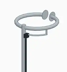
Early halo antennas[1] used two or more parallel loops, modeled after a 1943 patent[2] which was a folded dipole[3] bent into a circle.
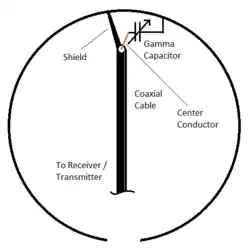
The two loop design broadens the SWR bandwidth and helps with impedance matching. More recent halo antennas have tended to use a single conductor fed with a gamma match.[lower-alpha 2] The newer approach uses less material and reduces wind load, but may be less mechanically robust, more narrow-banded, and requires a balun to prevent feed-line radiation.
Advantages and disadvantages of a halo antennas
Like all antenna designs, the halo antenna is a compromise that sacrifices one desirable quality for another even more desirable quality – for example halos are small and efficient, but only for a single frequency and a narrow band around it. The following sections discuss the advantages and disadvantages of halo antennas both for practical and theoretical issues.
Advantages
- The halo, as a larger antenna, is more efficient than a small loop.
- On the VHF bands and above, the physical diameter of a halo is small enough to be effectively used as a mobile antenna.
- Towards the horizon, the pattern is omnidirectional to within 3 dB or less, and that can be evened out by making the loop slightly smaller and adding more capacitance between the element tips. Not only will that even out the gain, it will reduce the largely-wasted upward radiation.[lower-alpha 3]
- When fed with a gamma match, the radiating element of the halo is at DC ground, which tends to reduce static buildup.
- Halos pick up less ignition noise from vehicles when mounted atop vehicle roofs than whip antennas.[4]
- Halos may be stacked for additional gain. This reduces the high angle radiation, but has little or no effect on the shape of the radiation pattern in the plane of the antenna.[lower-alpha 3]
- A well-constructed halo presents a good match to 50 ohm coaxial cable.[5]
Disadvantages
- Radiation from horizontal halos has almost no vertical polarization component. One can expect a large signal loss when the other station uses vertical polarization.[4]
- The halo antenna is structurally rigid; if attached to a vehicle, it may suffer damage from tree branches or other obstacles, unlike a whip antenna which bends and springs back.
- A halo antenna is a resonant antenna, providing best performance only around one frequency. On the other hand, a small transmitting loop can be tuned over a 3:1 frequency range with a variable capacitor.[lower-alpha 4]
- For mobile use, the halo is rather conspicuous compared to the much more common vertical whip antenna, and may attract unwanted attention.
- A halo antenna is not as efficient for skywave communications as a horizontal small loop, other things being equal, since more of its signal is sent upward instead of outward, wasting signal power “warming the clouds”.
Notes
- Note carefully that for all antenna types, for pattern and performance measurement antenna size is measured as a fraction (or multiple) of the length of waves passing through it; hence any one antenna’s effective “size” changes depending on the frequency the attached radio is operating on.
- The gamma match is only a typical feature of modern halos; it is not essential. There are other, less common methods of feeding halos that work just as well, or better.
- High angle radiation is not useful for VHF communications, except for signalling fast-orbiting spacecraft with a fixed antenna; for that special case, a radiation pattern that uniformly covers the entire sky is convenient.
- The feasible transmitting frequencies are those that make the small loop circumference between about 1/10 and 1/3 wavelength. ([wavelength] = 299.79 meters⁄[frequency in MHz] = 983.563 feet⁄[frequency in MHz]) The highest operating frequency is determined by the minimum capacity setting of the variable capacitor; the lowest frequency by the maximum capacity available and by how much loss is acceptable as reduced radiation resistance makes the efficiency very low. A more often used, somewhat conservative range is 1/8 to 1/4 wavelength. For receiving, a much lower frequency range is practical, with the circumference down to perhaps 1/16 wavelength. There is no such latitude with a halo antenna: It can only be (very nearly) 1/2 wavelength.
References
- Stites, Francis H. (October 1947). "A Halo for Six Meters". QST Magazine, p. 24.
- US patent 2324462, Leeds, L.M. & Scheldorf, M.W., "High frequency antenna system", issued 1943-07-13, assigned to General Electric Company
- "Folded Dipole". Antenna Theory.
- Tildon, Edward P. (December 1956). "Polarization effects in VHF mobile". QST Magazine. pp. 11–13.
- Danzer, Paul (September 2004). "A 6 meter halo". QST Magazine. pp. 37–39.
External links
- "Construct a halo antenna for two meters". kr1st.com.
- "Another two meter VHF loop design". fedler.com.