Antenna types
In radio systems, many different antenna types are used with specialized properties for particular applications. Antennas can be classified in various ways. The list below groups together antennas under common operating principles, following the way antennas are classified in many engineering textbooks.[1][2][3]
The dipole, monopole, array and large loop antenna types below typically function as resonant antennas; waves of current and voltage bounce back and forth between the ends, creating standing waves along the elements. Aperture antennas can be resonant or not. Traveling wave antennas are nonresonant types, the current and voltage waves travel in one direction along the antenna elements.
Isotropic
An isotropic antenna (isotropic radiator) is a hypothetical antenna that radiates equal signal power in all directions. It is a mathematical model that is used as the base of comparison to calculate the directionality or gain of real antennas. No real antenna can produce a truly isotropic radiation pattern, but the isotropic radiation pattern serves as a "worst case" reference for comparing the degree to which other antennas, regardless of type, can project radiation in one direction.
Nearly isotropic antennas can be constructed using multiple small elements, and regardless of type, any antenna very much smaller than a wavelength (say, ≲ 1/16 wave) will be approximately isotropic. The smaller the antenna, the more nearly isotropic it will be. Nearly isotropic antennas are used as reference antennas for testing other antennas and for field strength measurements, and for backup antennas on satellites which work without the satellite being oriented towards a communication station.
An "isotropic antenna" should not be confused with an "omnidirectional antenna"; an isotropic antenna radiates equal power in all three dimensions, while an omnidirectional antenna radiates equal power in all horizontal directions, with the power radiated varying with elevation angle, but decreasing to zero along the antenna's vertical axis.
Dipole
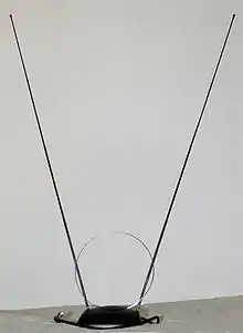 "Rabbit ears" dipole variant for VHF television reception
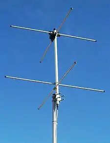 Two-element turnstile antenna for reception of weather satellite data, 137 MHz. Has circular polarization.
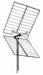 Corner reflector UHF TV antenna with "bowtie" dipole driven element at its center
The dipole is the prototypical antenna on which a large class of antennas are based. A basic dipole antenna consists of two conductors (usually metal rods or wires) arranged symmetrically, with one side of the balanced feedline from the transmitter or receiver attached to each.[2][4] The most common type, the half-wave dipole, consists of two resonant elements just under a quarter wavelength long. This antenna radiates maximally in directions perpendicular to the antenna's axis, giving it a small directive gain of 2.15 dBi. Although half-wave dipoles are used alone as omnidirectional antennas, they are also a building block of many other more complicated directional antennas.
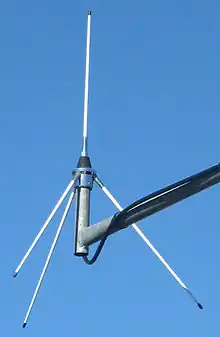
- Turnstile – Two dipole antennas mounted at right angles, fed with a phase difference of 90°. This antenna is unusual in that it radiates in all directions (no nulls in the radiation pattern), with horizontal polarization in directions coplanar with the elements, circular polarization normal to that plane, and elliptical polarization in other directions. Used for receiving signals from satellites, as circular polarization is transmitted by many satellites.
- Corner reflector – A directive antenna with moderate gain of about 8 dBi often used at UHF frequencies. Consists of a dipole mounted in front of two reflective metal screens joined at an angle, usually 90°. Used as a rooftop UHF television antenna and for point-to-point data links.
- Patch (microstrip) – A type of antenna with elements consisting of metal sheets mounted over a ground plane. Similar to dipole with gain of 6–9 dBi. Integrated into surfaces such as aircraft bodies. Their easy fabrication using PCB techniques have made them popular in modern wireless devices. Often combined into arrays.
Monopole
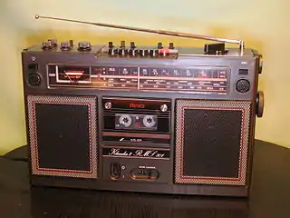 Quarter-wave whip antenna on an FM radio for 88-108 MHz
 VHF ground plane antenna
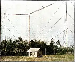
 Mast radiator antenna of medium wave AM radio station, Germany
 Folded unipole with skirt wires connected at a midpoint on the tower
A monopole antenna consists of a single conductor such as a metal rod, usually mounted over the ground or an artificial conducting surface (a so-called ground plane).[2][5] One side of the feedline from the receiver or transmitter is connected to the conductor, and the other side to ground or the artificial ground plane. The radio waves reflected from the ground plane seem to come from an image antenna below the ground, with the monopole and its image forming a dipole, so the monopole antenna has a radiation pattern identical to the top half of the pattern of a similar dipole antenna. Since all of the equivalent dipole's radiation is concentrated in a half-space, the antenna has twice (3 dB increase of) the gain of a similar dipole, not considering losses in the ground plane.
The most common form is the quarter-wave monopole which is one-quarter of a wavelength long and has a gain of 5.12 dBi when mounted over a ground plane. Monopoles have an omnidirectional radiation pattern, so they are used for broad coverage of an area, and have vertical polarization. The ground waves used for broadcasting at low frequencies must be vertically polarized, so large vertical monopole antennas are used for broadcasting in the MF, LF, and VLF bands. Small monopoles are used as nondirectional antennas on portable radios in the HF, VHF, and UHF bands.
- Whip – Type of antenna used on mobile and portable radios in the VHF and UHF bands such as boom boxes, consists of a flexible rod, often made of telescoping segments.
- Rubber ducky – Most common antenna used on portable two-way radios and cordless phones due to its compactness, consists of an electrically short wire helix. The helix adds inductance to cancel the capacitive reactance of the short radiator, making it resonant. Very low gain.
- Ground plane – a whip antenna with several rods extending horizontally from base of whip attached to the ground side of the feedline. Since whips are mounted above ground, the horizontal rods form an artificial ground plane under the antenna to increase its gain. Used as base station antennas for land mobile radio systems such as police, ambulance and taxi dispatchers.
- Mast radiator – A radio tower in which the tower structure itself serves as the antenna. Common form of transmitting antenna for AM radio stations and other MF and LF transmitters. At its base the tower is usually, but not necessarily, mounted on a ceramic insulator to isolate it from the ground.
- Folded unipole antenna – is a modified mast antenna, usually grounded at its base, augmented by one or several parallel wires called "skirt wires" that attach to the mast part-way up the antenna. The skirt wires can attach at any height between part-way up and the top of the mast. One or more of the skirt wires is fed with the signal, similar to a gamma match. The number and relative thickness of the mast and the skirt wires adjusts the impedance magnitude at the feedpoint. Further, the fed wire(s) and the mast form a vertically aligned loop which inductively loads the antenna, with the inductance controlled by the height of the attachment point.
- T and inverted L – Consist of a long horizontal wire suspended between two towers with insulators, with a vertical wire hanging down from it, attached to a feedline to the receiver or transmitter. Used on LF and VLF bands. The vertical wire serves as the radiator. Since at these frequencies the vertical wire is electrically short, much shorter than a quarter wavelength, the horizontal wire(s) serve as a capacitive "hat" to increase the current in the vertical radiator, increasing the gain. Very narrow bandwidth, requires loading coil to tune out any remaining capacitive reactance. Requires low resistance ground.
- Inverted F – Combines the advantages of the compactness of inverted-L antenna, and the good matching of the F-type antenna. The antenna is grounded at the base and fed at some intermediate point. The position of the feed point determines the antenna impedance. Thus, matching can be achieved without the need for a separate matching network.
- Umbrella – Very large wire transmitting antennas used on VLF bands. Consists of a central mast radiator tower attached at the top to multiple wires extending out radially from the mast to ground, like a tent or umbrella, insulated at the ends. Extremely narrow bandwidth, requires large loading coil and low resistance counterpoise ground. Used for long range military communications.
Array
 VHF collinear array of folded dipoles
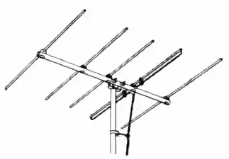
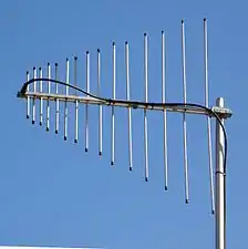 Log-periodic dipole array covering 140-470 MHz
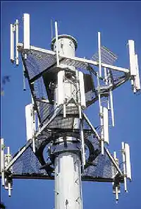 Sector antennas (white bars) on cell phone tower. Collinear arrays of dipoles, these radiate a flat, fan-shaped beam.
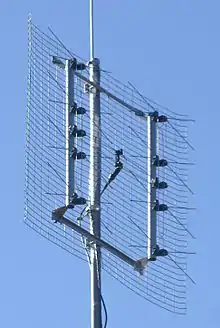 Reflective array UHF TV antenna, with bowtie dipoles to cover the UHF 470-890 MHz band
 US Air Force PAVE PAWS phased array radar antenna for ballistic missile detection, Alaska. The two circular arrays are each composed of 2677 crossed dipole antennas.
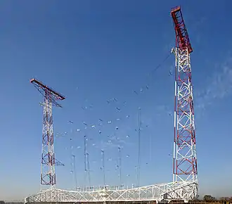 Curtain array shortwave transmitting antenna, Austria. Wire dipoles suspended between towers
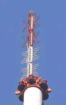 Four-bay batwing television broadcasting antenna, Germany.
Array antennas consist of multiple simple antennas working together as a single compound antenna. Broadside arrays consist of multiple identical driven elements, usually dipoles, fed in phase, radiating a beam perpendicular to the antenna plane. Endfire arrays are fed out-of-phase, with the phase difference corresponding to the distance between them; they radiate within the antenna plane.[2][6][7] Parasitic arrays consist of multiple antennas, usually dipoles, with one driven element and the rest parasitic elements, which radiate a beam along the line of the antennas.
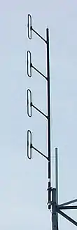
- Collinear – Consist of a number of dipoles in a vertical line. It is a high-gain omnidirectional antenna, meaning more of the power is radiated in horizontal directions and less wasted radiating up into the sky or down onto the ground. Gain of 8–10 dBi. Used as base station antennas for land mobile radio systems such as police, fire, ambulance, and taxi dispatchers, and sector antennas for cellular base stations.
- Yagi–Uda – One of the most common directional antennas at HF, VHF, and UHF frequencies. Consists of multiple half-wave dipole elements in a line, with a single driven element and multiple parasitic elements which serve to create a uni-directional or beam antenna. These typically have gains between 10–20 dBi depending on the number of elements used, and are very narrow band (with a usable bandwidth of only a few percent) though there are derivative designs which relax this limitation. Used for rooftop television antennas, point-to-point communication links, and long distance shortwave communication using skywave ("skip") reflection from the ionosphere.
- Log-periodic dipole array – Often confused with the Yagi-Uda, this consists of many dipole elements along a boom with gradually increasing lengths, all connected to the transmission line with alternating polarity. It is a directional antenna with a wide bandwidth. This makes it ideal for use as a rooftop television antenna, although its gain is much less than a Yagi of comparable size.
- Reflective array – Multiple dipoles in a two-dimensional array mounted in front of a flat reflecting screen. Used for radar and UHF television transmitting and receiving antennas.
- Phased array – A high gain antenna used at UHF and microwave frequencies which is electronically steerable. It consists of multiple dipoles in a two-dimensional array, each fed through an electronic phase shifter, with the phase shifters controlled by a computer control system. The beam can be instantly pointed in any direction over a wide angle in front of the antenna. Used for military radar and jamming systems.
- Curtain array – Large directional wire transmitting antenna used at HF by shortwave broadcasting stations. It consists of a vertical rectangular array of wire dipoles suspended in front of a flat reflector screen consisting of a vertical "curtain" of parallel wires, all supported between two metal towers. It radiates a horizontal beam of radio waves into the sky above the horizon, which is reflected by the ionosphere to Earth beyond the horizon.
- Half-square antenna – A pair of ground-isolated, quarter-wave vertical monopoles, whose tops are connected by a line one half-wavelength long. The verticals are the radiators and function as a two-element array, similar to the bobtail curtain. The structure is shaped like the Greek letter Π (not to be confused with the Half-Loop antenna described below). The top-to-top connecting wire serves as a phased feedline, or an auxiliary feed, which puts the point of maximum current at the top of each monopole. Neither monopole element has a wire connection to the ground beneath it. Top-fed monopoles produce a strong signal low to the horizon, as opposed to an ordinary bottom-fed monopoles. The feedpoint for the combined system may be placed at any of several locations.[8]
- Batwing or superturnstile – A specialized antenna used in television broadcasting consisting of perpendicular pairs of dipoles with radiators resembling bat wings. Multiple batwing antennas are stacked vertically on a mast to make VHF television broadcast antennas. Omnidirectional radiation pattern with high gain in horizontal directions. The batwing shape gives them wide bandwidth.
- Microstrip – an array of patch antennas on a substrate fed by microstrip feedlines. Microwave antenna that can achieve large gains in compact space. Ease of fabrication by PCB techniques have made them popular in modern wireless devices. Beamwidth and polarization can be actively reconfigurable.
Loop

Loop antennas consist of a loop (or coil) of wire. Loop antennas interact directly with the magnetic field of the radio wave, rather than its electric field, making them relatively insensitive to electrical noise within about a quarter-wavelength of the antenna.[2][9][10] There are essentially two broad categories of loop antennas: large loops (or full-wave loops) and small loops. Only one design, a "halo" antenna, that is usually called a loop does not fit into either the large or small loop categories.
Large loops
Full loops have the highest radiation resistance, and hence the highest efficiency of all antennas: Their radiation resistances are several hundreds of Ohms, whereas dipoles and monopoles are tens of Ohms, and small loops are a few ohms, or even fractions of an Ohm.[10]
- Large loops – Loops with perimeter of a full wavelength, two wavelengths, or any whole-number multiple of a full-wavelength, are naturally resonant and act somewhat similarly to the full-wave or multi-wave dipole. When it is necessary to distinguish them from small loops, they are called "full-wave" loops.[lower-alpha 1][2][9]
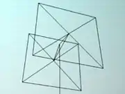
- Quad – Although "quad" can refer to a single quadrilateral-shaped loop, the term usually refers to two or more loops stacked side by side; at first glance, quads resemble a box kite frame. One loop in the quad is connected to the feedline and functions as the driver for the antenna and is the main signal radiator, while the others are parasitic element that act as resonators, increasing the gain.[2][9][10] Quad antennas function analogously to Yagi-Uda antennas made with loops,[2][9][10] and are similarly used as a directional antennas on the HF bands for shortwave communication. They are sometimes preferred for longer wavelengths because (if square) they are half as wide as a Yagi.[2][9][10]
- Half-loop – A ground-mounted upper half of a full-wavelength loop antenna (not to be confused with a half-square array). The full loop is cut at two opposite points along its perimeter, and the lower half is omitted. It is shaped like the Greek letter Π or an upside-down capital letter U, and is the loop antenna analog of a ground-mounted monopole antenna. Like a vertical monopole, the missing lower half of the antenna is replaced by its ground-plane image. If shaped like a half of a square, a half-loop can operate either as a loop antenna or, on its first harmonic, as a dipole antenna whose ends have been bent over and grounded, depending on the form and location of the feed-point.[8]
In between
- Halo antennas – Loops that are exactly one half-wavelength in perimeter – with a small gap cut in the loop – are called "halo antennas" and are intermediate in form and function between small and large loops. They are often described as a half-wavelength dipole that has been folded into a circle, rather than being a true loop antenna.[2][9][10][11]
Small loops
The great disadvantage of any small antenna, including small loops, is a very small radiation resistance – typically much smaller than the loss resistance, making small loops very inefficient for transmitting. However, small loops are very effective receiving antennas, especially at low frequencies, where all feasible antennas are "small" compared to a wavelength.
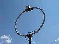
- Small loops – If the loop perimeter is smaller than a half-wavelength, the loop must be modified in some way to make it resonant, if resonance is necessary. Small loops are called "magnetic loops", and if modified for resonance they are also called "tuned loops". Their directionality and radiation efficiency is drastically different from full-wave loops. Small loops are widely used as compact direction finding antennas.[2][9][10]
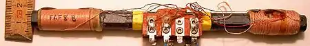
- Ferrite (loopstick) – Loopstick antennas are omnidirectional around their axes, and are premier examples of small loop antennas. They are the magnetic analogue of the short dipole antenna. These are used as the receiving antenna in most consumer AM radios operating in the medium wave broadcast band (and lower frequencies).[lower-alpha 2] Wire is coiled around a ferrite core which greatly increases the coil's inductance and its effective signal-capturing area. The radiation pattern is maximum at directions perpendicular to the ferrite rod. The null direction of ferrite core antennas are bi-directional and much sharper than the maximal directionality. This often makes the direction of the null more useful for locating a signal source than the direction of the strongest signal. The null direction of small loops can also be exploited to reject unwanted signals from an interfering station or noise source.[2][9][10]
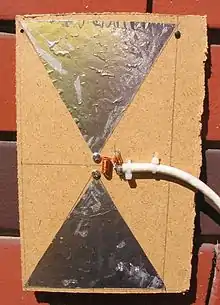
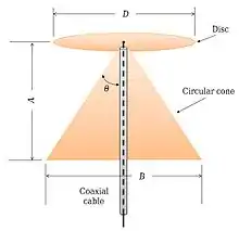
Conical
- biconical antenna is a dipole-like antenna made of two cones, aligned along the same axis and oriented tip-to-tip.
- Butterfly antenna is a two-dimesional (flat) biconical antenna.
- discone antenna is half of a biconical with a flat disc mounted above the cone
Aperture
 NASA Cassegrain parabolic spacecraft communication antenna, Australia. Uses X band, 8 – 12 GHz. Extremely high gain ~70 dBi.
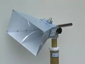 Microwave horn antenna bandwidth 0.8–18 GHz
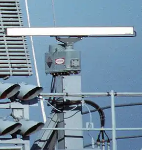
 Dielectric lens antenna used in millimeter wave radio telescope
Aperture antennas are the main type of directional antennas used at microwave frequencies and above.[2][12] They consist of a small dipole or loop feed antenna inside a three-dimensional guiding structure large compared to a wavelength, with an aperture to emit the radio waves. Since the antenna structure itself is nonresonant they can be used over a wide frequency range by replacing or tuning the feed antenna.
- Parabolic – The most widely used high gain antenna at microwave frequencies and above. Consists of a dish-shaped metal parabolic reflector with a feed antenna at the focus. It can have some of the highest gains of any antenna type, up to 60 dBi, but the dish must be large compared to a wavelength. Used for radar antennas, point-to-point data links, satellite communication, and radio telescopes
- Horn – a simple antenna with moderate gain of 15 to 25 dBi that consists of a flaring metal horn attached to a waveguide. Used for applications such as radar guns, radiometers and as feed antennas for parabolic dishes.
- Slot – consists of a waveguide with one or more slots cut in it to emit the microwaves. Linear slot antennas emit narrow fan-shaped beams. Used as UHF broadcast antennas and marine radar antennas.
- Lens – a lens antenna consists of layer of dielectric or a metal screen or multiple waveguide structure of varying thickness in front of a feed antenna, which acts as a lens which refracts the radio waves, focusing them on the feed antenna.
- Dielectric resonator – consists of small ball or puck-shaped piece of dielectric material excited by aperture in waveguide Used at millimeter wave frequencies
Traveling wave
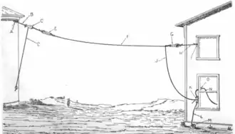
 Animation showing a Beverage antenna .
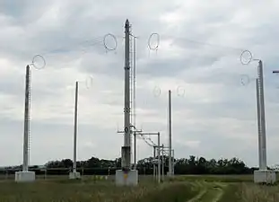 Quadrant antenna, similar to rhombic, at an Austrian shortwave broadcast station. Radiates horizontal beam at 5-9 MHz, 100 kW
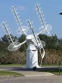 Array of four axial-mode helical antennas used for satellite tracking, France
Unlike the above antennas, traveling-wave antennas are not resonant so they have inherently broad bandwidth.[2][13] They are typically wire antennas that are multiple wavelengths long, through which the voltage and current waves travel in one direction, instead of bouncing back and forth to form standing waves as in resonant antennas. They have linear polarization (except for the helical antenna). Unidirectional traveling-wave antennas are terminated by a resistor at one end equal to the antenna's characteristic resistance, to absorb the waves from one direction. This makes them inefficient as transmitting antennas.
- Beverage – Simplest unidirectional traveling-wave antenna. Consists of a straight wire one to several wavelengths long, suspended near the ground, connected to the receiver at one end and terminated by a resistor equal to its characteristic impedance, 400–800 Ω at the other end. Its radiation pattern has a main lobe at a shallow angle in the sky off the terminated end. It is used for reception of skywaves reflected off the ionosphere in long distance "skip" shortwave communication.
- Rhombic – Consists of four equal wire sections shaped like a rhombus. It is fed by a balanced feedline at one of the acute corners, and the two sides are connected to a resistor equal to the characteristic resistance of the antenna at the other. It has a main lobe in a horizontal direction off the terminated end of the rhombus. Used for skywave communication on shortwave bands.
- Leaky wave – Microwave antennas consisting of a waveguide or coaxial cable with a slot or apertures cut in it so it radiates continuously along its length.
- Helical (axial mode) – Consists of a wire in the shape of a helix mounted above a reflecting screen. It radiates circularly polarized waves in a beam off the end, with a typical gain of 15 dBi. It is used at VHF and UHF frequencies where antenna sizes are feasible. Often used for satellite communication, which uses circular polarization because it is insensitive to the relative rotation on the beam axis. When a helical antenna has about 10 turns or more, each turn a full wavelength, then it is a form of traveling-wave antenna. If it only has a few turns (or just one) and the turns' totaled circumference is one or a few wavelengths, then it is some variety of a large loop antenna. When the totaled circumference of all the turns taken together is less than one wavelength, then the helix is a continuously-loaded monopole, called a "rubber ducky antenna", or a "Slinky" antenna, or a "broomstick" antenna.
Other antenna types
The following antenna, called "the odd bit of wire" by Moxon (1982),[14] doesn't easily fit into any of the categories above.
- Random wire – This describes the typical antenna used to receive shortwave radio, consisting of a random length of wire either strung outdoors between supports or indoors in a zigzag pattern along walls, connected to the receiver at one end. The antenna typically will have complex radiation patterns with several lobes at angles to the wire, in different directions for each fold in the antenna. Random wire antennas typically are categorized as folded monopole antennas if their lengths are two wavelengths or less, but operate similarly to traveling-wave antennas when they are laid out in a straight line several wavelengths long.
Notes
- The popular "quad" antenna design is necessarily a full-wave loop, so no other distinction is needed.
- A notable exception are car radios, which require an antenna outside the metal car chassis which blocks AM and longer-wave reception.
References
- Bevelaqua, Peter J. "Types of Antennas". Antenna Theory. Antenna-theory.com. Archived from the original on 30 June 2015. Retrieved 28 June 2015.
Peter Bevelaqua's private website.
- Aksoy, Serkan (2008). "Antennas" (PDF). Electrical Engineering Department. Lecture Notes-v.1.3.4. Gebze, Turkey: Gebze Technical University. Archived from the original (PDF) on 22 February 2016. Retrieved 29 June 2015.
- Balanis, Constantine A. (2005). Antenna Theory: Analysis and Design. 1 (3rd ed.). John Wiley and Sons. p. 4. ISBN 047166782X.CS1 maint: ref=harv (link)
- Bevelaqua, Peter. "Dipole Antenna". Antenna-Theory.com. Archived from the original on 17 June 2015.
- Bevelaqua, Peter. "Monopole Antenna". Antenna-Theory.com. Archived from the original on 15 June 2015.
- Bevelaqua, Peter. "Antenna Arrays". Antenna-Theory.com. Archived from the original on 25 April 2017.
- Balanis 2005, pp. 283–371
- Severns, Rudy (N6LF) (1996). "Using the half-square antenna for low-band DXing". In Straw, R. Dean (N6BV); Roznoy, Rich (KA1OF) (eds.). ARRL Antenna Compendium. 5. Newington, CT: American Radio Relay League. pp. 35–44. ISBN 0-87259-562-5.
- Bevelaqua, Peter. "Loop Antennas". Antenna-Theory.com. Archived from the original on 17 June 2015.
- Silver, H. Ward, ed. (2011). ARRL Antenna Book for Radio Communications (22nd ed.). Newington, CT: American Radio Relay League. Chapter 5, Section 9.6, Section 11.6, Section 16.5, Section 20.6, Chapter 22. ISBN 978-0-87259-680-1.
- Balanis 2005, pp. 231–275
- Balanis 2005, pp. 653–728
- Balanis 2005, pp. 549–602
- Moxon, Les (G6XN) (1995) [1982]. HF Antennas for all Locations (2nd ed.). Potters Bar, Hertfordshire, UK: Radio Society of Great Britain. ISBN 1-872309-15-1.