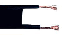
Twin-lead
Twin-lead cable is a two-conductor flat cable used as a balanced transmission line to carry radio frequency (RF) signals. It is constructed of two stranded or solid copper or copper-clad steel wires, held a precise distance apart by a plastic (usually polyethylene) ribbon. The uniform spacing of the wires is the key to the cable's function as a transmission line; any abrupt changes in spacing would reflect some of the signal back toward the source. The plastic also covers and insulates the wires. It is available with several different values of characteristic impedance, the most common type is 300 ohm.
| Part of a series on |
| Antennas |
|---|
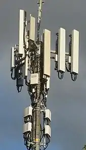 |
Twin lead is mainly used as an antenna feedline at shortwave and VHF frequencies, to connect radio receivers and transmitters to their antennas. It can have significantly lower signal loss than miniature flexible coaxial cable, the main alternative type of feedline at these frequencies; for example, type RG-58 coaxial cable loses 6.6 dB per 100 m at 30 MHz, while 300 ohm twin-lead loses only 0.55 dB.[1] 300 ohm twin lead is widely used to connect FM radios to their antennas, and was previously used to connect television antennas to televisions until it was replaced by coaxial cable. However, it is more vulnerable to interference; proximity to metal objects will inject signals into twin-lead that would be blocked out by coaxial cable. It therefore requires spacing around rain gutters, and standoff insulators along metal support masts.
Characteristics and uses
Twin lead and other types of parallel-conductor transmission line are mainly used to connect radio transmitters and receivers to their antennas. Parallel transmission line has the advantage that its losses are an order of magnitude smaller than that of coaxial cable, the main alternative form of transmission line. Its disadvantages are that it is more vulnerable to interference, and must be kept away from metal objects which can cause power losses. For this reason, when installed along the outside of buildings and on antenna masts, standoff insulators must be used. It is also common practice to twist the twin lead on long free standing lengths to further reject any induced imbalances to the line.
Twin-lead is supplied in several different sizes, with values of 600, 450, 300, and 75 ohm characteristic impedance. The most common, 300 ohm twin-lead, was once widely used to connect television sets and FM radios to their receiving antennas. 300 ohm twin-lead for television installations has been largely replaced with 75 ohm coaxial cable feedlines. Twin-lead is also used in amateur radio stations as a transmission line for balanced transmission of radio frequency signals.
The characteristic impedance of twin-lead is a function of the wire diameter and its spacing; in 300 ohm twin-lead, the most common type, the wire is usually 20 or 22 gauge, about 7.5 mm (0.30 inches) apart.[2] This is well matched with the natural impedance of a folded dipole antenna, which is normally around 275 ohms. Twin-lead generally has higher impedance than the other common transmission wiring, coaxial cable (coax). The widely used RG-6 coax has a characteristic impedance of 75 ohms, which requires the use of a balun to match impedance when used with common antenna types.
How it works
Twin lead is a form of parallel-wire balanced transmission line. The separation between the two wires in twin-lead is small compared to the wavelength of the radio frequency (RF) signal carried on the wire.[3] The RF current in one wire is equal in magnitude and opposite in direction to the RF current in the other wire. Therefore, in the far field region far from the transmission line, the radio waves radiated by one wire are equal in magnitude but opposite in phase (180° out of phase) to the waves radiated by the other wire, so they superpose and cancel each other.[3] The result is that almost no net radio energy is radiated by the line.
Similarly, any interfering external radio waves will induce equal, in phase RF currents, traveling in the same direction, in the two wires. Since the load at the destination end is connected across the wires, only differential, oppositely-directed currents in the wires create a current in the load. Thus the interfering currents are canceled out, so twin lead does not tend to pick up radio noise.
However, if a piece of metal is located sufficiently close to a twin-lead line, within a distance comparable to the wire spacing, it will be significantly closer to one wire than the other. As a result, the RF current induced in the metal object by one wire will be greater than the opposing current induced by the other wire, so the currents will no longer cancel. Thus nearby metal objects can cause power losses in twin lead lines, through energy dissipated as heat by induced currents. Similarly, radio noise originating in cables or metal objects located near the twin-lead line can induce unbalanced currents in the wires, coupling noise into the line.
In order to prevent power from being reflected from the load end of the line, causing high SWR and inefficiency, the load must have an impedance which matches the characteristic impedance of the line. This causes the load to appear electrically identical to a continuation of the line, preventing reflections. Similarly, to transfer power efficiently into the line, the source must also match the characteristic impedance. To connect balanced transmission line to unbalanced line like coaxial cable, a device called a balun must be used.
Ladder line
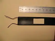
Ladder line or "window line" is a variation of twin lead which is constructed similarly, except that the polyethylene webbing between the wires which holds them apart has rectangular openings ("windows") cut in it.[2][4] The line consists of two insulated wires with "rungs" of plastic holding them together every few inches, giving it the appearance of a ladder. The advantage of the "windows" is that they lighten the line, and also reduce the amount of surface on which dirt and moisture can accumulate, making ladder line less vulnerable to weather-induced changes in characteristic impedance.[2] The most common type is 450 ohm ladder line, which has a conductor spacing of about an inch.[2]
Ladder line may also be manufactured or DIY-constructed as "open wire line" consisting of two parallel wires featuring widely spaced plastic or ceramic insulating bars and having a characteristic impedance of 600 ohms or more.[5]
Impedance matching
As a transmission line, transmission efficiency will be maximum when the impedance of the antenna, the characteristic impedance of the twin-lead line and the impedance of the equipment are the same. For this reason, when attaching a twin-lead line to a coaxial cable connection, such as the 300 ohm twin-lead from a domestic television antenna to the television's 75 ohm coax antenna input, a balun with a 4:1 ratio is commonly used. Its purpose is double: first, it transforms twin-lead's 300 ohm impedance to match the 75 ohm coaxial cable impedance; and second, it transforms the balanced, symmetric transmission line to the unbalanced coax input. In general, when used as a feedline, twin-lead (especially ladder line versions) has a higher efficiency than coaxial cable when there is an impedance mismatch between the feedline and the source (or sink). For receive-only use this merely implies that the system can communicate under slightly less optimal conditions; for transmit use, this can often result in significantly less energy lost as heat in the transmission line.
Twin-lead also can serve as a convenient material with which to build a simple folded dipole antenna. Such antennas may be fed either by using a 300 ohm twin-lead feeder or by using a 300-to-75-ohm balun and using coaxial feedline and will usually handle moderate power loads without overheating.
Characteristic impedance
The characteristic impedance of a parallel-wire transmission line like twin lead or ladder line depends on its dimensions; the diameter of the wires d and their separation D. This is derived below.
The characteristic impedance of any transmission line is given by

where for twin-lead line the primary line constants are


where the surface resistance of the wires is

and where d is the wire diameter and D is the separation of the wires measured between their centrelines.
Neglecting the wire resistance R and the leakage conductance G, this gives

where Z0 is the impedance of free space (approximately 377 Ω), εr is the effective dielectric constant (which for air is 1.00054). If the separation D is much greater than the wire diameter d then this is approximately

The separation needed to achieve a given characteristic impedance is therefore

The dielectric material between the two conductors with either twin-lead or ladder line is not all air. The effect of a "mixed" dielectric, part air and part polyethylene or other plastic, is that the actual impedance will fall somewhere between the value calculated assuming all air or all polyethylene. Published or measured values for Z0 will be more accurate than the formula values.
Antennas
Twin-lead can be connected directly to a suitably designed antenna:
- a Windom antenna whose resonant impedances cluster around 300 Ω,
- a folded dipole, whose characteristic impedance in free space is around 400 Ω,
- a dipole, although the center impedance at resonance is approximately 73 Ω in free space, so a T-match or Y-match feed will probably be necessary,
- a Yagi antenna or similar balanced antenna, although some special impedance matching arrangement at the feedpoint will be necessary, due to the Yagi's typically low impedance.
References
| Wikimedia Commons has media related to Twin-lead cables. |
- "Why ladder line?". Highveld Amateur Radio Club.
- Straw, R. Dean, Ed. (2000). The ARRL Antenna Book, 19th Ed. USA: American Radio Relay League. pp. 24.16–17. ISBN 0-87259-817-9.
- Straw, R. Dean, Ed. (2000). The ARRL Antenna Book, 19th Ed. USA: American Radio Relay League. p. 24.1. ISBN 0-87259-817-9.
- Ford, Steve (December 1993). "The Lure Of Ladder Line" (PDF). QST. ARRL. Retrieved September 16, 2011.
- Danzer, Paul (April 2004). "Open Wire Feed Line—A Second Look". QST. ARRL. Retrieved September 16, 2011.
- Balanced Transmission Line in Current Amateur Practice, ARRL Antenna Compendium, Volume 6. Wes Stewart, N7WS.
- ARRL Handbook for Amateur Radio. Newington, CT: American Radio Relay League. 2000. p. 19.3.
