Traffic light control and coordination
The normal function of traffic lights requires more than slight control and coordination to ensure that traffic and pedestrians move as smoothly, and safely as possible. A variety of different control systems are used to accomplish this, ranging from simple clockwork mechanisms to sophisticated computerized control and coordination systems that self-adjust to minimize delay to people using the junction.
History
The first automated system for controlling traffic signals was developed by inventors Leonard Casciato and Josef Kates and was used in Toronto in 1954.[1][2][3]
Phases and stages
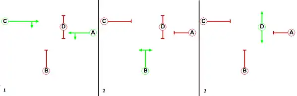
Traffic controllers use the concept of phases, which are directions of movement grouped together.[4][5] For instance, a simple T-junction may have three vehicle movement phases, one for each arm of the junction. There may be additional phases for other movements such as pedestrians, cyclists, bus lanes or tramways.
A stage is a group of non-conflicting phases which move at the same time. [6]
In Australia and New Zealand, the terminology is different. A "phase" is a period of time during which a set of traffic movements receive a green signal - equivalent to the concept of a "stage" in UK and USA. One electrical output from the traffic signal controller is called a "signal group" - similar to the UK and USA concept of "phase".
Traffic controller systems
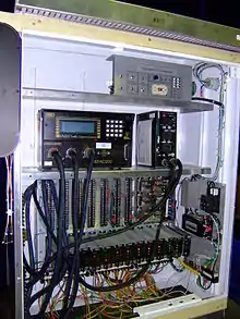
A traffic signal is typically controlled by a controller mounted inside a cabinet.[7] Some electro-mechanical controllers are still in use (New York City still had 4,800 as of 1998, though the number is lower now due to the prevalence of the signal controller boxes[8]). However, modern traffic controllers are solid state. The cabinet typically contains a power panel, to distribute electrical power in the cabinet; a detector interface panel, to connect to loop detectors and other detectors; detector amplifiers; the controller itself; a conflict monitor unit; flash transfer relays; a police panel, to allow the police to disable the signal; and other components.[7]
In the United States, controllers are standardized by the NEMA, which sets standards for connectors, operating limits, and intervals.[7] The TS-1 standard was introduced in 1976 for the first generation of solid-state controllers.[9]
Solid state controllers are required to have an independent conflict monitor unit (CMU), which ensures fail-safe operation. The CMU monitors the outputs of the controller, and if a fault is detected, the CMU uses the flash transfer relays to put the intersection to FLASH, with all red lights flashing, rather than displaying a potentially hazardous combination of signals. The CMU is programmed with the allowable combinations of lights, and will detect if the controller gives conflicting directions a green signal, for instance.
In the late 1990s, a national standardization effort known as the Advanced transportation controller (ATC) was undertaken in the United States by the Institute of Transportation Engineers.[9] The project attempts to create a single national standard for traffic light controllers. The standardization effort is part of the National Intelligent transportation system program funded by various highway bills, starting with ISTEA in 1991, followed by TEA-21, and subsequent bills. The controllers will communicate using National Transportation Communications for ITS Protocol (NTCIP), based on Internet Protocol, ISO/OSI, and ASN.1.[9]
Traffic lights must be instructed when to change stage and they are usually coordinated so that the stage changes occur in some relationship to other nearby signals or to the press of a pedestrian button or to the action of a timer or a number of other inputs.
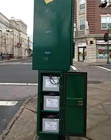
Battery backup
In the areas that are prone to power interruptions, adding battery backups to the traffic controller systems can enhance the safety of the motorists and pedestrians. In the past, a larger capacity of uninterruptible power supply would be required to continue the full operations of the traffic signals using incandescent lights. The cost for such system would be prohibitive. After the newer generations of traffic signals that use LED lights which consume 85-90% less energy, it is now possible to incorporate battery backups into the traffic light systems. The battery backups would be installed in the traffic controller cabinet or in their own cabinet adjacent to the controller.
The battery backups can operate the controller in emergency mode with the red light flashing or in fully functional mode. In 2004, California Energy Commission recommended to have local governments to convert their traffic lights to LEDs with battery backups. This would lower the energy consumption and enhance the safety at major intersections. The recommendation was for a system which provides fully functional traffic signals for two hours after the power outage. Then the signals will have flashing red lights for another two hours.[10]
Fixed time control
In traffic control, simple and old forms of signal controllers are what are known as electro-mechanical signal controllers. Unlike computerized signal controllers, electro-mechanical signal controllers are mainly composed of movable parts (cams, dials, and shafts) that control signals that are wired to them directly. Aside from movable parts, electrical relays are also used. In general, electro-mechanical signal controllers use dial timers that have fixed, signalized intersection time plans. Cycle lengths of signalized intersections are determined by small gears that are located within dial timers. Cycle gears, as they are commonly known, range from 35 seconds to 120 seconds. If a cycle gear in a dial timer results in a failure, it can be replaced with another cycle gear that would be appropriate to use. Since a dial timer has only one signalized intersection time plan, it can control phases at a signalized intersection in only one way. Many old signalized intersections still use electro-mechanical signal controllers, and signals that are controlled by them are effective in one way grids where it is often possible to coordinate the signals to the posted speed limit. They are however disadvantageous when the signal timing of an intersection would benefit from being adapted to the dominant flows changing over the time of the day.[11]
Coordinated control
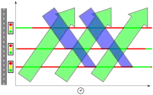
Attempts are often made to place traffic signals on a coordinated system so that drivers encounter a green wave, a long string of green lights (the technical term is progression). The distinction between coordinated signals and synchronized signals is very important. Synchronized signals all change at the same time and are only used in special instances or in older systems. Coordinated (progressed) systems are controlled from a master controller and are set up so lights "cascade" (progress) in sequence so platoons of vehicles can proceed through a continuous series of green lights. A graphical representation of phase state on a two-axis plane of distance versus time clearly shows a "green band" that has been established based on signalized intersection spacing and expected vehicle speeds.[12] In some countries (e.g. Germany, France and the Netherlands), this "green band" system is used to limit speeds in certain areas. Lights are timed in such a way that motorists can drive through without stopping if their speed is lower than a given limit, mostly 50 km/h (30 mph) in urban areas. This system is known as "grüne Welle" in German, "vague verte" in French, or "groene golf" in Dutch (English: "green wave"). Such systems were commonly used in urban areas of the United States from the 1940s, but are less common today. In the UK, Slough in Berkshire had part of the A4 experimented on with this. Many US cities set the green wave on two-way streets to operate in the direction more heavily traveled, rather than trying to progress traffic in both directions. But the recent introduction of the flashing yellow arrow (see Traffic-light signalling and operation) makes the lead-lag signal, an aid to progression, available with protected/permissive turns.[12][13]
In modern coordinated signal systems, it is possible for drivers to travel long distances without encountering a red light. This coordination is done easily only on one-way streets with fairly constant levels of traffic. Two-way streets are often arranged to correspond with rush hours to speed the heavier volume direction. Congestion can often throw off any coordination, however. On the other hand, some traffic signals are coordinated to prevent drivers from encountering a long string of green lights. This practice discourages high volumes of traffic by inducing delay yet preventing congestion or to discourage use of a particular road. This is often done at the request of local residents in areas that have a lot of commuter "just passing through" traffic. Speed is self-regulated in coordinated signal systems; drivers traveling too fast will arrive on a red indication and end up stopping, drivers traveling too slowly will not arrive at the next signal in time to utilize the green indication. In synchronized systems, however, drivers will often use excessive speed in order to get through as many lights as possible.
More recently even more sophisticated methods have been employed. Traffic lights are sometimes centrally controlled by monitors or by computers to allow them to be coordinated in real time to deal with changing traffic patterns.[14] Video cameras, or sensors buried in the pavement can be used to monitor traffic patterns across a city. Non-coordinated sensors occasionally impede traffic by detecting a lull and turning red just as cars arrive from the previous light. The most high-end systems use dozens of sensors and cost hundreds of thousands of dollars per intersection, but can very finely control traffic levels. This relieves the need for other measures (like new roads) which are even more expensive.
- Increasing the traffic handling capacity of roads
- Reducing collisions and waiting time for both vehicles and pedestrians[17]
- Encouraging travel within the speed limit to meet green lights
- Reducing unnecessary stopping and starting of traffic - this in turn reduces fuel consumption, air and noise pollution, and vehicle wear and tear
- Reducing travel time
- Reducing driver frustration and road rage
Examples:
- New York City: 7,660 (of a total of 12,460) signalized intersections are controlled by a central computer network and monitored by traffic management centers.[8][18]
- Toronto: 83% of its signals are controlled by the Main Traffic Signal System (MTSS). 15% also use the SCOOT (Split Cycle and Offset Optimization Technique), an adaptive signal control system.[19]
- Sydney: 3,400 traffic signals co-ordinated by the Sydney Co-ordinated Adaptive Traffic System (SCATS). Designed and developed by RTA, the system was first introduced in 1963 and progressively developed since then. By October 2010, SCATS was licensed to 33,200 intersections in 144 cities across 24 countries worldwide, including Singapore, Hong Kong, Dublin, Tehran and Minneapolis and Detroit.[16][20][21]
- Melbourne: 3,200 traffic lights across Victoria, including regional areas such as Geelong and Ballarat, using SCATS. Some 500 intersections also have tram and bus priority.[22]
- Adelaide: 580 sets of coordinated traffic lights throughout the metropolitan region managed by the Adelaide Coordinated Traffic Signal (ACTS) System.[15]
Adaptive control
- Meadowlands Adaptive Signal System for Traffic Reduction (MASSTR) - New Jersey Meadowlands Commission monitors in their Lyndhurst administration building this "intelligent transportation system", the first of its kind in the state, with traffic controlled intersections and vehicle detectors in the Meadowlands. As of 2013, it is in operation and plans to cover 128 intersections by 2014. To reduce delays due to the planned two-year closure of the northbound lanes of the Pulaski Skyway that will start around March 2014, this system will synchronize traffic lights at an additional 15 intersections along US 1/9 Truck and Route 440 in Kearny Point and Jersey City.[23][24][25][26]
- Midtown in Motion - New York City's adaptive traffic control system that employs multiple technologies. Cameras, microwave motion sensors and radio-frequency identification (RFID) E-ZPass tag readers are used as inputs as a mean to for monitoring traffic flow. The data is fed through the government-dedicated broadband wireless infrastructure to the traffic management center to be used in adaptive traffic control of the traffic lights.[27]
- Scalable Urban Traffic Control
- Sydney Coordinated Adaptive Traffic System
Other types of control
- Failures: If power is still available, a flashing amber light is used to warn of an intersection. Methods to distinguish the main road from the secondary road (and hence right of way) include using yield (give way) signs, stop signs or a flashing red light on the secondary road as well as written signage. In some countries including Australia, the road rules outline procedures such as giving way to the right.
- Part-time operation: Some traffic lights will not operate at night or when traffic is very light. Some may only operate at particular set times (e.g. during working hours of a major factory) or only during special events such as sports or exhibitions. When not operating, the same measures as with failures are used. Part-time operation has advantages and disadvantages.[28][29]
- Railroad preemption: Traffic signals are activated to coincide with the approach of a train, often where the intersection is near a rail crossing. See also Railroad preemption
- Bus and Transport Priority: Traffic signals are activated to coincide with the arrival of a bus or tram along a busway, bus lane or tramway. See also Bus priority
- Emergency Vehicles Some lights outside of fire or rescue stations have no green, as they may turn only amber and then red when fire trucks, ambulances, or other emergency vehicles or the like are exiting the station en route to an emergency. See also Traffic signal preemption
- Speed signs are a rarely used variant to give drivers a recommended speed to approach the next traffic light in its green phase.
Design software
Traffic light systems are designed using software such as LINSIG, TRANSYT or VISSIM.
References
- Engelmann, Frederick C. (1996) A History of the Austrian Migration to Canada, Carleton University Press, ISBN 978-0-88629-283-6, p. 184
- McLean, James W. (1966) "The Phony Ogre of Automation", Montreal Gazette, February 26, 1966, retrieved 2010-10-31
- "Josef Kates Found Ways to Unsnarl Traffic and Solve Business Problems With Computers". James R. Hagerty, Wall Street Journal, July 27, 2018
- Department for Transport, General Principles of Traffic Control by Light Signals TAL 1/06 https://www.gov.uk/government/publications/traffic-advisory-leaflets-1989-to-2009
- Sanderson Associates, http://www.traffic-signal-design.com/terminology_main.htm
- Basics Archived 2008-12-16 at the Wayback Machine, Traffic Signal Training, NIATT / University of Idaho
- Traffic Signals 101, Minnesota Department of Transportation, 2006
- Choreographing the Dance of Traffic Lights, New York Times, September 17, 1998
- Traffic Signal Standards Archived 2008-06-26 at the Wayback Machine, National Transportation Operations Coalition
- "Senate Bill 84 XX Battery Backup Program for Light Emitting Diode (LED) Traffic Signals" (PDF). California Energy Commission. May 2004. Retrieved 20 January 2014.
- Learning Traffic Light Control Policies URL accessed 2009-03-06
- Robinson, Larry. "Traffic Signal Progression". Retrieved 22 May 2014.
- Robinson, Larry. "Lead-Lag with Flashing Yellow Arrow". Retrieved 22 May 2014.
- SCOOT system
- Department for Transport, Energy and Infrastructure (2002-08-23). "Adelaide Coordinated Traffic Signal (ACTS) System". Transport Network - Traffic Operations. Government of South Australia. Archived from the original on 2009-05-26. Retrieved 2010-12-11.
- Roads and Traffic Authority. "SCATS - Product Features". SCATS. NSW Government. Retrieved 2010-12-11.
- Xiao-Feng Xie, et al. Real-time traffic control for sustainable urban living. IEEE International Conference on Intelligent Transportation Systems (ITSC), Qingdao, China, 2014: 1863-1868.
- NYCDOT Infrastructure & Traffic Signals
- City of Toronto. "Traffic - Frequently asked questions". Transportation - Traffic. City of Toronto. Retrieved 2010-12-11.
- Roads and Traffic Authority. "Hands on control: New South Wales Transport Management Centre" (PDF). TMC. NSW Government. Retrieved 2010-12-11.
- Roads and Traffic Authority. "Review of Operations: Transport" (PDF). 2009-10 Annual Report. NSW Government. Retrieved 2010-12-11.
- VicRoads. "Traffic Signals SCATS". Road Management & Design. Victoria Government. Archived from the original on 2011-02-26. Retrieved 2010-12-11.
- "Meadowlands Adaptive Signal System for Traffic Reduction" (PDF). New Jersey Meadowlands Commission. July 2013. Archived from the original (PDF) on October 24, 2013. Retrieved October 16, 2013.
- Frassinelli, Mike (September 5, 2013). "During Pulaski Skyway Closure, Traffic Lights to Be Adjusted on Local Roads". The Star-Ledger. Newark, NJ. Retrieved October 12, 2013.
- Vena, Joseph R. (September 5, 2013). "'Adaptive' signals will speed up traffic in Jersey City and Kearny during Pulaski Skyway construction". The Jersey Journal. Jersey City, NJ. Retrieved October 16, 2013.
- Maag, Christopher (November 29, 2013). "High-tech signal system helps speed Meadowlands traffic". The Record. Woodland Park, NJ. Retrieved November 30, 2013.
- "New York's award-winning traffic control system". ITS International. January–February 2013. Retrieved 3 May 2014.
- "Removal Of Signal Flashing Mode During Late-Night / Early-Morning Operation". US Federal Highway Administration Office of Safety Design. Retrieved 2011-10-23.
- Various authors. "Flashing signals". ITETRAFFIC (Mailing list). Retrieved 2011-10-23.
External links
- Koonce, Peter; et al. (June 2008). Traffic Signal Timing Manual (Report). United States Federal Highway Administration. FHWA-HOP-08-024. Retrieved 2010-04-05.
